10
clock circuit in the shutdown situation. The input is from battery.
(5)The stepper motor driving circuit: adopts the specialized stepper motor controlling
circuit. Under the control of CPU, the speed, subdivision, current ratio and damping ratio
can be adjusted, depending on requirements.
b. The Main Testing Points
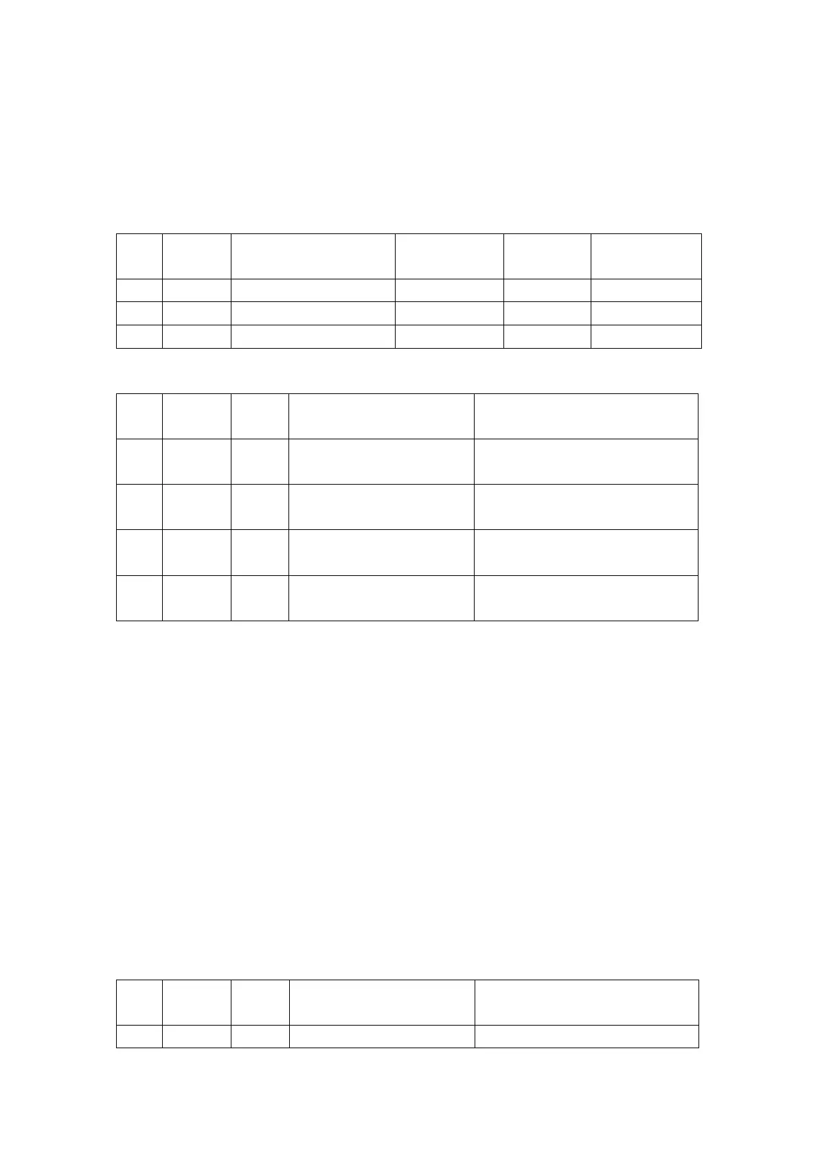
c. Number and Definition of the Circuit Board Sockets
Socket to inlet the DC
output voltage
Connect J1 in the AC/DC board
Socket to connect the
power board
Connect J5 in the power board
Socket to connect the
power board
Connect J8 in the power board
Socket to connect the
interface board
Connect CON2 in the interface
board
2.4.3 The Power Board
a. The Circuit Introduction
The power control board has following main functions:
(1) Control the CPU circuit: controls on/off and stepper motor, receives and processes
signals from the compression bar sensors, and communicates with interface CPU of
SYS02 circuit.
(2)A function of signal switch board: collects signals from every sensor and all kinds of
DC power, distributes the corresponding signal to SYS02 circuit board, DC/DC power
board, stepper motor, alarm light and speaker, RS485 serial port and external interface,
etc.
(3)Charging circuit and boosted circuit of the super-capacitor.
(4)MCU control circuit of buzzer alarm.
b. The Main Testing Points: none.
c. Number and Definition of the Circuit Board Sockets
Connect J2 in the SYS02 board