37
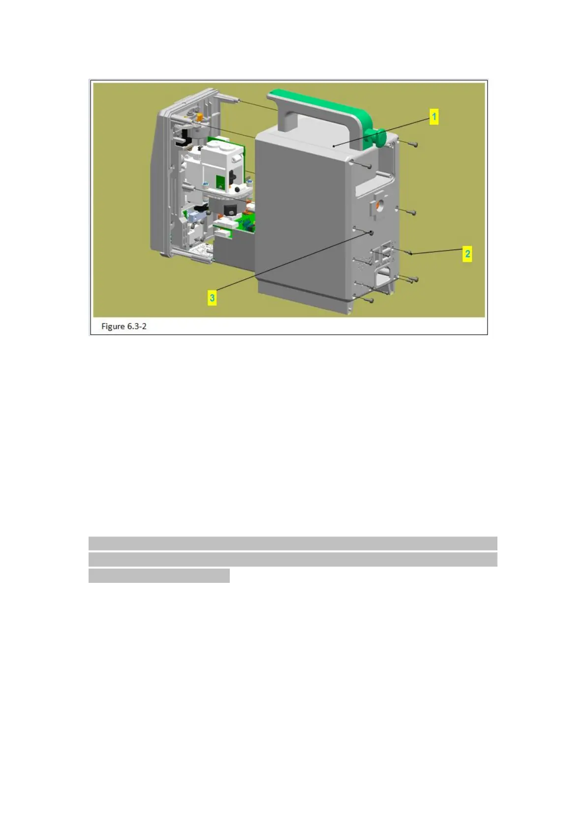
Figure 6.3-2 Notes:
Code Name
2 – PB2.3 PB2.3 tapping screw
1) Use phillips screwdriver to take out the 6 PB2.3 tapping screws (figure 6.3-2/code name
2) in the rear cover (figure 6.3-2/code name 1).
2)Use phillips screwdriver to take out the 6 PT3.0tapping screws (figure 6.3-2/code name
3) in the rear cover.
3)Balance the rear cover with left hand, then use screwdriver with right hand to stick the
inner side of the AC power socket. Use a uniform force to inner cover and separate the
rear cover carefully.
Attention: be careful to remove the rear cover, avoid pulling out other components inside
the device. After removing the rear cover, please take a picture first to know well the circuit
connections and wire bindings.
6.3.3 Remove the Baffle