39
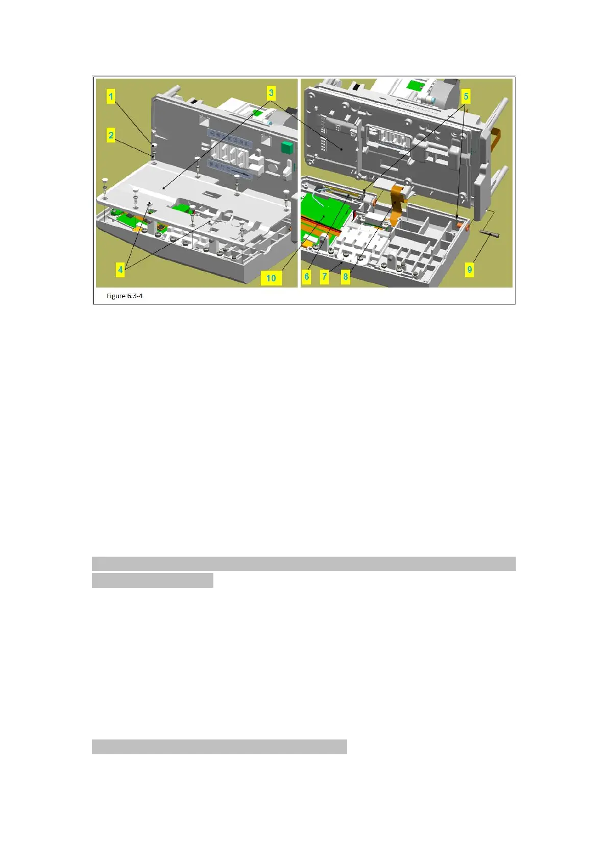
Figure 6.3-4 Notes:
Code Name
1 –Round Decorative Cover
3 –Square Decorative Cover
8 –Flat Cable Sealing Groove
1)Use pilers to take down the 9 round decorative covers (figure 6.3-4/code name 1) and 2
square decorative covers (figure 6.3-4/code name 3) in the cover board (figure 6.3-4/code
name 4).
Attention: use pilers tip to insert between the decorative covers and stick them up, avoid
breaking the cover board.
2)Use phillips screwdriver to remove the 7 PB2.3 tapping screws.
3)Take out the cover board lightly.
Attention: Do not miss the magnets in the cover board.
4)Remove the FRC flat cable (figure 6.3-4/code name 6) inside the cover board (figure
6.3-4/code name 5).
5)Remove the flat cable sealing groove (figure 6.3-4/code name 8) in the middle board
(figure 6.3-4/code name 7).
6)Pull out the bracket for PCB (figure 6.3-4/code name9) lightly, and pull out the FPC flat
cable at the same time.
Attention: take care the FPC flat cable not to be hung.