16
Option 3 - N+P
This option presents the combination of both of the previous cases, NPN and PNP,
however, the alarm lines are hard-driven to either 24VDC or GND.This conguration is
the same for both alarm pins (pin-2 and pin-4).
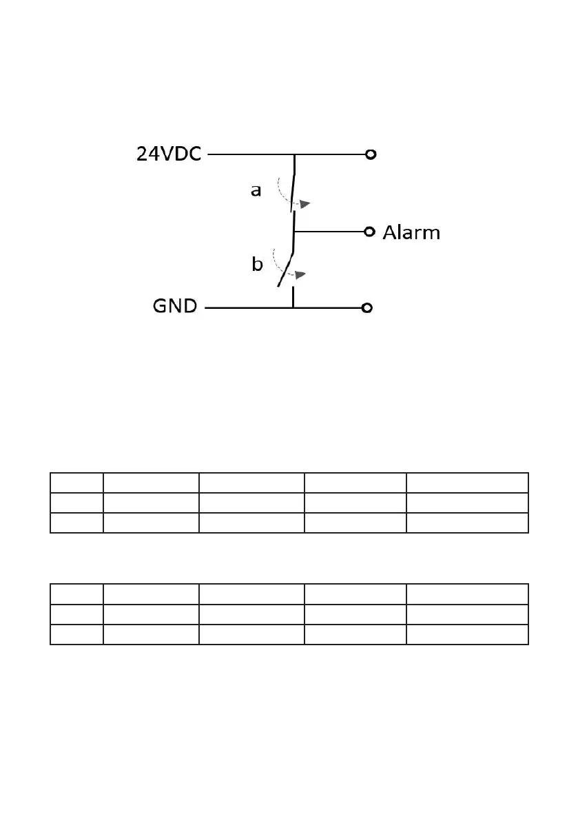
Simplied Diagram of N+P output
Logic Table
Alarm True = Hi
Start State Solid Green Flashing Red Solid Red
White Hi Lo Hi Hi
Black Hi Lo Lo Hi
Alarm True = Lo
Start State Solid Green Flashing Red Solid Red
White Hi Hi Lo Lo
Black Hi Hi Hi Lo
Note: On unit power-up, both alarm pins remain in Hi state for up to 60 seconds
before these are used as alarm pins.
Note: When ‘a’ is closed, ‘b’ is
open and vice versa.