Do you have a question about the Meech HYPERION 233v4 and is the answer not in the manual?
Details the items included as standard with the 233v4 controller.
Lists optional accessories available for the 233v4 controller.
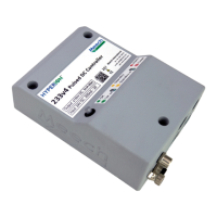
Describes the physical appearance and dimensions of the 233v4 controller unit.
Details the adjustable high voltage output range and configuration.
Explains the simplified low voltage wiring via M8 connector for easy installation.
Outlines the meaning of different LED colors and patterns for operation status.
Describes the output signals for ioniser cleaning needs or detected faults.
Instructions on how to physically mount the controller unit using provided holes.
Procedure for connecting ionisers to the controller using grey HT connections.
Details the critical grounding requirements for the 233v4 and its power supply.
Diagram and details of the M8 4 pin connector on the controller.
Specifies the function and color for each pin in the M8 4 pin connector.
Guidance on connecting the controller using a Meech branded 24V DC power supply.
Responsibility for checking and connecting a customer-provided 24V DC power supply.
Details the function of pin 2 (white) and pin 4 (black) for alarm reporting.
Explains the configuration where alarm logic is active high.
Explains the configuration where alarm logic is active low.
Details the NPN transistor-driven output configuration for alarm pins.
Details the PNP transistor-driven output configuration for alarm pins.
Details the combined NPN and PNP hard-driven output configuration.
Initial steps and preset configurations for the 233v4 controller.
Procedure for setting the correct start voltage and target ion output.
Guidance on setting the variable output frequency based on ioniser and distance.
How to adjust the output bias for neutralisation accuracy.
Procedure to set the ion output level threshold for alerts.
Details on using the 3-pin socket for remote on/off functionality.
Step-by-step guide to connect the BarMaster to the controller.
Adjusting the output frequency for optimal performance.
Adjusting the output balance for precise ion neutralisation.
Setting the alarm point for ion level monitoring.
Understanding ion level readings and what they indicate about ioniser performance.
Procedure for resetting the ion reference level after calibration.
Guide to understanding the LED status lights for fault diagnosis.
Steps to clean the ioniser if a performance drop is detected.
| Power Consumption | 15W |
|---|---|
| Output Voltage | 24V DC |
| Supported Protocols | Modbus TCP, Modbus RTU |
| Storage Temperature | -20°C to +70°C |
| Communication Interface | Ethernet, RS485 |