MAC/MTT-OPS-1
26 FEB 2019
SECTION 2
System Description
2-20
WATER CANNON SYSTEM
The system is comprised of a water cannon
(hydraulic or electric), hydraulic control valve
assembly or logic box, butterfly valve assembly,
nozzle and controls.
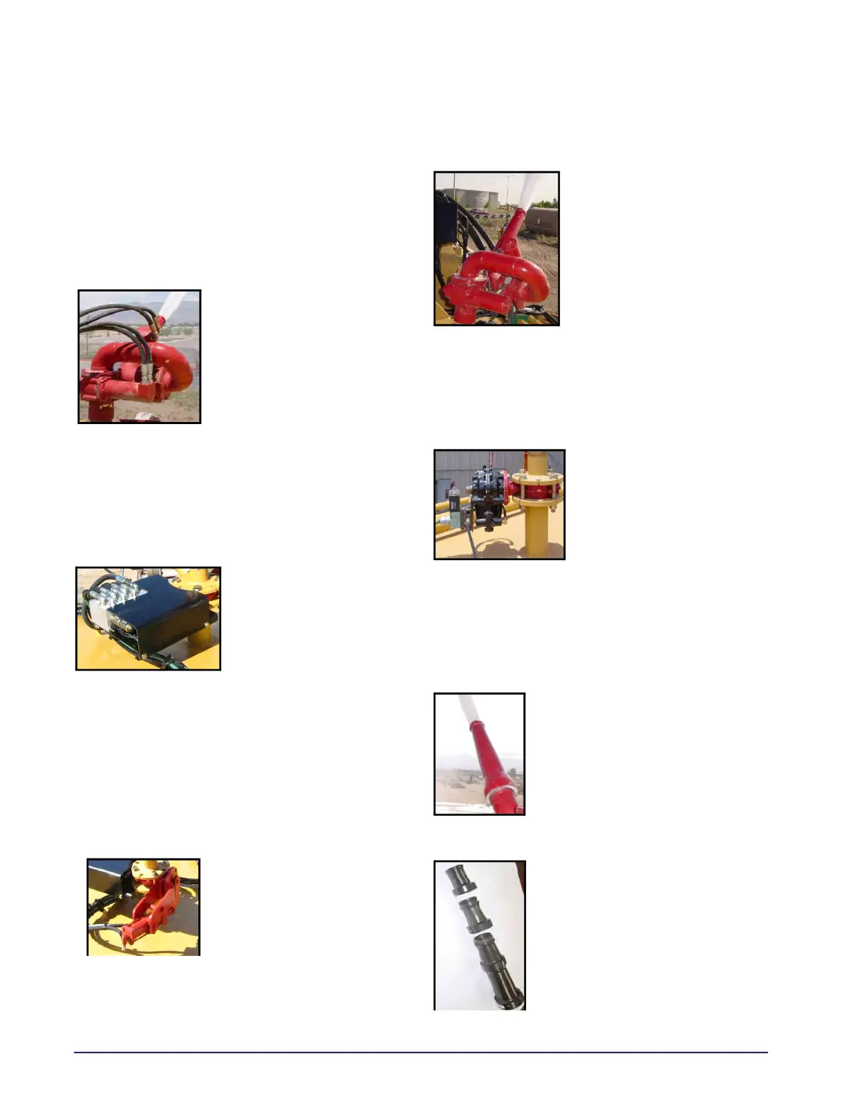
Water Cannon (Hydraulic)
A metal waterway that directs
a stream of water in both
elevation (up-down) and
rotation (right-left). Hydraulic
motors move the waterway
based upon hydraulic flow
from the hydraulic control
valve assembly as
commanded by the cab control joystick. The water
cannon is threaded to a flanged pipe that mounts
directly above the BFV. The water cannon also
provides mounting for a variety of different
nozzles.
Hydraulic Control Valve Assembly
The assembly contains
three hydraulic solenoid
valves that direct hydraulic
pressure to the hydraulic
motors on the water
cannon and BFV cylinder
as commanded by the cab control box. A pressure
relief valve is incorporated in the manifold block to
protect the water cannon system against any over
pressurization conditions. The assembly is
mounted to the tank lower flange and receives
hydraulic pressure from the vehicle hydraulic
pump.
Hydraulic BFV Assembly
A hydraulically operated valve
that opens or closes to control
water flow to the water
cannon. The hydraulic
cylinder receives hydraulic
pressure from the hydraulic
control valve or solenoid control box assembly as
commanded by the cab control water cannon
switch. The assembly is clamped between upper
and lower pipe flanges.
Water Cannon (Electric)
A metal waterway that directs
a stream of water in both
elevation (up-down) and
rotation (right-left). 24 VDC
electric motors move the
waterway based upon filtered
electronic signals from the
logic box as commanded by
the cab control joystick. The
water cannon is threaded to a flanged pipe that
mounts directly above the BFV. The water cannon
also provides mounting for a variety of different
nozzles.
Electro-Pneumatic BFV Assembly
An electro-pneumatic valve
that controls the flow of
water to the water cannon. A
24 volt DC solenoid receives
commands from a cab
control MONITOR / BFV
switch through the logic box
to route pressurized air to an air chamber which
opens or closes a 3” valve. The assembly is
clamped between upper and lower pipe flanges.
Water Cannon Nozzles And Stream Shapers
Straight/Smooth Bore Nozzle
A cone shaped 1.5” diameter nozzle
that directs water flow. The nozzle
has a built in stream shaper that
smooths water flow to increase
water stream distance.
Straight/Smooth Bore (Stackable)
A segmented cone shaped nozzle
that directs water flow. The nozzle
opening is adjusted by removing
segments to acquire the most
efficient nozzle opening for a given
water pump operating pressure.
Nozzle segment diameters are 1?”,
1½”, 1¾” and 2”. The nozzle requires
and in-line stream shaper to
increase water stream distance.