6-1
MAC/MTT-OPS-1
26 FEB 2019
SECTION 6
Employment
Contents
DESCRIPTION
This section provides descriptions, guidance, and
techniques used when employing the MEGA spray
system features. These best practices will provide
operators with several different choices that will
result in maximum system performance in most
applications with ever changing conditions.
SPRAY HEADS
Spray head adjustment and fine tuning techniques
are key factors in optimizing water distribution and
preventing over-watering of roadways. The MEGA
spray heads are mounted to base plate assemblies
connected to the water discharge piping. MEGA
spray heads can be rotated on the base plate to
direct the discharge fan in the necessary directions
for optimum spray pattern. The spray heads
incorporate an adjustable ring to control the spray
intensity and fan width. The opening in the base of
the MEGA spray head will allow for approximately
a 90° maximum fan width as illustrated below.
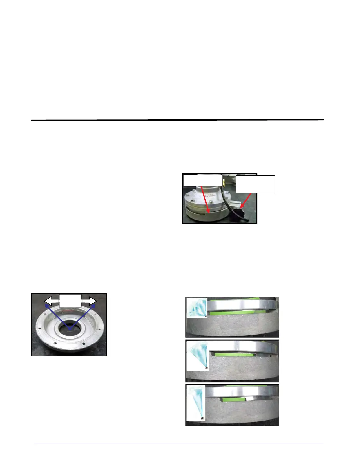
Fan Width And Spray Intensity Adjustment
The spray head adjusting ring is used to control the
fan width and spray intensity to match most
applications. These settings can be changed by
first loosening the adjusting ring knob and then
rotating the adjusting ring to the desired position.
The following images are examples of the
adjustment ring at the “fine spray” setting with
varying fan widths. The “fine spray” setting is
typically used for reduced water volumes and a
larger pattern, and is best suited for lower vehicle
speeds and low water pump rpm.
Fine Spray (1/4” Slot Height)
90
o
Fan
Width
Adjusting Ring
Adjusting Ring
Knob
90
o
Fan Width
45
o
Fan Width
20
o
Fan Width
Description...................................................................6-1
Spray Heads.................................................................6-1
Dust Suppression.......................................................6-4
Intermittent Spray.....................................................6-5
Troubleshooting.........................................................6-6
Speed Based Programming....................................6-6
Distance Based Programming...............................6-7
Tank Drain.....................................................................6-8
Dump Bar......................................................................6-8
Fire Suppression System..........................................6-9