7
APPLICATION
The DET14C / DET24C digital earth clamp meters are particularly
suitable for measuring earth resistance in various installations
such as buildings, pylons and RF transmitter sites without system
disconnection. In addition, they can be used for the inspection
and verification of lightning protection systems and virtually any
installation where a current loop can be generated.
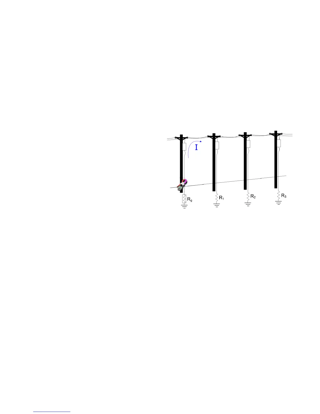
Principle of Operation
A defined test voltage is injected into the system under test using
a voltage transducer coil to induce a current, I, to flow which can
be measured by the current sensing coil. The resistance follows
from Ohm’s law, R = V/I.
The system shown in Figure 5 can be simplified to the resistance
of the electrode under test, Rg and the resistance of the other
electrodes in parallel, i.e. R1 || R2 || R3… || Rn. Therefore, the
current induced by the test voltage is I=V/[Rg+(R1 || R2 ||
R3… || Rn)]. It follows that as the resistance of the other
electrodes in parallel approaches zero, then the resistance
measured, approaches the value of the electrode under test.
Figure 5: Example earthing system suitable for
clamp meter