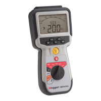
The Megger MIT415 / MIT417 is an insulation and continuity tester designed for electrical professionals. This user guide provides essential information on its operation, safety warnings, technical specifications, and maintenance procedures.
Function Description
The MIT415 / MIT417 is primarily used for measuring insulation resistance and continuity in electrical circuits. It also offers AC/DC voltage and frequency measurements. The device is equipped with various features to ensure user safety and accurate testing.
Insulation Resistance Testing:
The tester performs insulation resistance measurements at high DC voltages, making it crucial to observe all safety precautions. It offers standard insulation resistance testing, as well as timed modes for Polarization Index (PI) and Dielectric Absorption Ratio (DAR) tests.
- Standard Insulation Resistance Testing: Involves connecting test probes to an isolated circuit, selecting the desired test voltage, and holding the [TEST] button. The insulation resistance value, actual test voltage, and leakage current can be displayed. A lock function allows for continuous testing.
- Timed Tests (t, PI, DAR):
- Timed (t) Test: Performed over a user-defined period.
- Polarization Index (PI): Calculates the ratio of insulation resistance values at 1 minute (t1) and 10 minutes (t2). PI = 10 minute value / 1 minute value.
- Dielectric Absorption Ratio (DAR): Calculates the ratio of insulation resistance values at 30 seconds (t1) and 60 seconds (t2). DAR = 60 second value / 30 second value.
During insulation tests, a flashing symbol indicates the presence of a test voltage. Capacitive circuits are automatically discharged after the test button is released.
Continuity Testing:
The device measures continuity in ohms and features an audible buzzer.
- Lead Nulling: Allows users to zero out the test lead resistance for accurate measurements.
- Buzzer Function: Can be enabled/disabled, with an adjustable pass threshold (default 2 Ω). The buzzer sounds if the resistance result is less than the set value.
- Test Current Display: The auxiliary display shows the actual test current during continuity tests, which depends on the circuit's resistance.
AC/DC Voltage and Frequency Measurements:
The instrument can measure both AC and DC components of the supply voltage (AC+DC) in TRMS mode, and only the DC component in DC mode.
- Voltage Range: Up to 600 V phase to earth or phase to phase.
- Frequency Display: In TRMS mode, the measured frequency (Hz) is displayed simultaneously with the voltage.
- Automatic Inhibition: In continuity mode, if a voltage greater than 25 V is detected, testing is automatically inhibited, and voltage measurement is displayed instead.
Resistance Measurements (kΩ Range):
For measuring resistance in the kilohm range, the user selects the kΩ position and connects the test leads to the isolated conductors. The result is displayed automatically.
Important Technical Specifications
Insulation:
- Nominal Test Voltages (MIT415): 10 V, 25 V, 50 V, 100 V, 250 V, 500 V
- Nominal Test Voltages (MIT417): 10 V, 25 V, 50 V, 100 V, 250 V, 500 V, 1000 V
- Range Full Scale Accuracy: ±2% ±2 digits up to 100 MΩ.
- Accuracy per GΩ:
- 1000 volts: ±3% ±2 digits
- 500 volts: ±3% ±2 digits ±0.4%
- 250 volts: ±3% ±2 digits ±0.8%
- 100 volts: ±3% ±2 digits ±2.0%
- 50 volts: ±3% ±2 digits ±4.0%
- 25 volts: ±3% ±2 digits ±8%
- 10 volts: ±3% ±2 digits ±20%
- Analogue Range: 1 GΩ full scale
- Short Circuit Current: 2 mA +0% -50%
- Terminal Voltage: -0% +20% ±1V (Ii <1 mA)
- Test Current on Load: 1 mA at min. pass value of insulation specified in BS7671, HD384 and IEC364, EN61152-2, 2 mA max.
- EN61557 Operating Range: 0.10 MΩ to 1.00 GΩ
- Leakage Current Range: 10 μA to 2000 μA
- Leakage Current Accuracy: 10% ±3 digits
- Voltage Display Accuracy: 3% ±3 digits ±0.5% of rated voltage
- Dielectric Absorption Ratio (DAR): 60sec / 30sec ratio
Continuity:
- EN61557 Operating Range: 0.01 Ω to 99.9 Ω (0 to 100 Ω on analogue scale)
- Accuracy: ± 2% ± 2 digits (0 to 100 Ω)
- Open Circuit Voltage: 5 V ± 1 V
- Test Current: 205 mA (±5 mA) (0.01 Ω to 9.99 Ω); 20 mA (±1 mA) (10.0 Ω to 99.9 Ω)
- Lead Resistance Zeroing: Up to 9.99 Ω
- Buzzer Limits: Variable (1 Ω, 2 Ω, 5 Ω, 10 Ω, 20 Ω)
Resistance (kΩ):
- EN61557 Operating Range: 0.01 kΩ to 1000 kΩ (0 to 1 MΩ on analogue scale)
- Accuracy: ±3% up to 50 kΩ then ±5% ±2 digits
- Open Circuit Voltage: 5 V ± 1 V
- Short Circuit Current: 1.5 mA ±0.2 mA
Voltage Range:
- DC: 0 to 600 V d.c. ± 2% ± 2 digits
- TRMS Sinusoidal (40 – 400 Hz): 10 mV to 600 V TRMS ±2% ±2 digits
- Analogue Scale: 0 to 1000 V
- Unspecified Input Level: 0 – 10 mV (40 – 400 Hz)
- Non-sinusoidal Waveforms: ±3% ±2 digits 101 mV – 600 V TRMS; ±8% ±2 digits 10 mV – 100 mV TRMS
Default Voltmeter: Operates at >25 volts a.c. or d.c., on any range except OFF.
Frequency:
- 15-400 Hz (15 Hz - 99.9 Hz) ±0.5% ±1 digit
- (100 Hz to 400 Hz)
Power Supply:
- 5 x 1.5 V cells type IEC LR6 (AA, MN1500, HP7, AM3 R6HP) Alkaline. NiMH rechargeable cells may be used.
Battery Life:
- 2200 insulation tests with duty cycle of 5 sec on 55 sec off.
Dimensions: 220 x 92 x 50 mm (8.66 in x 3.63 in x 1.97 in)
Weight: 590 gms, 775 gms with boot (20.73 oz (27.22 oz))
Fuse: 500 mA (FF) 1000 V 32 x 6 mm ceramic fuse of high breaking capacity HBC 50 kA minimum. Glass fuses MUST NOT be fitted.
Safety Protection: Meets EN 61010-1 (1995) to 600 V phase to earth, Category IV.
E.M.C.: In accordance with IEC 61326 including amendment No.1.
Environmental:
- Operating Range: -20 °C to +55 °C
- Operating Humidity: 95% RH at 0 °C to +35 °C, 70% RH +35 °C to +55 °C
- Storage Temperature Range: -30 °C to +80 °C
- Calibration Temperature: +20 °C
- Maximum Altitude: 2000 m
- Dust and Water Protection: IP54
Usage Features
- LCD Display: Features an auxiliary digital display, continuity indicator, lock indicator, battery condition indicator, warning indicator, out of range indicator, lead null indicator, TRMS indicator, and audible alarm indicator.
- SP5 Switched Probe: Allows users to initiate tests directly from the probe, enhancing hands-free operation and safety.
- Setup Options: Users can adjust various threshold values and default settings, including:
- BUZ (Buzzer Threshold): Sets the top threshold for the continuity buzzer (1, 2, 5, 10, 20 Ω).
- Loc (Lock Button): Enables/disables the lock function (ON/OFF).
- ISC (Continuity Short-Circuit Current): Sets the maximum continuity short-circuit current (20 mA, 200 mA).
- User Guide: Provides detailed instructions for all functions and safety warnings.
- Accessories: Includes a 2-wire test lead set with crocodile clips, SP5 remote switch probe, calibration certificate, rubber boot, instrument case, and user guide. Optional fused 2-wire test lead sets are also available.
Maintenance Features
- Battery Condition Indicator: Displays battery charge level (100%, 75%, 50%) when the instrument is switched on.
- Battery Replacement: Instructions are provided for replacing the 5 x LR6 (AA) 1.5 V alkaline or 5 x 1.2 V NiMH rechargeable cells. Users are advised to disconnect test leads, switch off the instrument, and ensure correct polarity.
- Blown Fuse Indicator: A flashing symbol is displayed if the fuse is ruptured when checking by switching to an insulation range and pressing the TEST button.
- Fuse Replacement: Detailed instructions for replacing the 500 mA (FF) 1000 V 32 x 6 mm ceramic fuse.
- Preventive Maintenance: The instrument can be cleaned with a damp cloth; alcohol-based cleaners should not be used.
- WEE Directive and Battery Disposal: Information on proper disposal of the instrument and batteries in accordance with environmental regulations.
- Repair and Warranty: New instruments are guaranteed for 3 years. Instructions for returning an instrument for repair, including obtaining a Returns Authorisation number, are provided. Megger operates approved repair and calibration facilities.
Safety Warnings
- Always read and understand Safety Warnings and Precautions before use.
- The circuit under test must be switched off, de-energised, isolated, and proved dead before insulation and continuity tests.
- Avoid touching circuit connections, exposed-conductive-parts, and other metalwork during testing.
- The live circuit warning and automatic discharge are additional safety features and do not replace safe working practices.
- The voltage function only works if the instrument is functional and switched on.
- Capacitive circuits must be allowed to discharge after insulation tests before disconnecting leads.
- Do not use the instrument if any part is damaged.
- Ensure test leads, probes, and crocodile clips are in good order, clean, and free of damaged insulation.
- Keep hands behind probe/clip guards during testing.
- National Safety Authorities may recommend fused test leads for high-energy systems.
- Only use correctly rated replacement fuses to prevent safety hazards and damage.
- The battery cover must be in place during tests.
- The instrument must only be used by suitably trained and competent persons.
- Users should carry out valid risk assessments for electrical work to identify potential dangers.