42
15.3 Blown fuse indicator
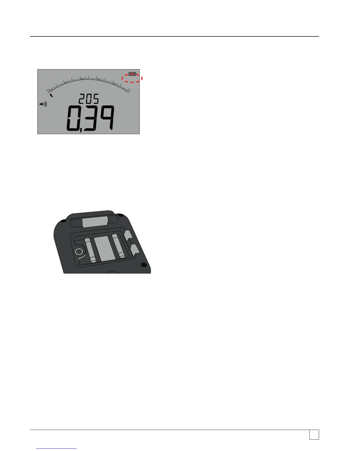
The blown fuse indicator is shown below:
z
f
100 0
8 00
6 004 00
2 00
0
W
W
Am
- Figure 48
This symbol operates on the continuity [W] range. The symbol indicates that one of the fuses in the instrument has failed.
15.4 Fuse replacement procedure
1. Switch off the instrument and disconnect the instrument from any electrical circuits.
2. Disconnect all test leads from the instrument.
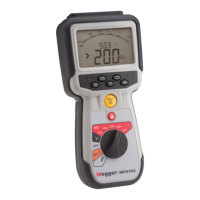
3. Remove the rear fuse cover. To remove the rear cover, undo the screw on the rear of the small fuse cover and lift the cover off,
as below:
- Figure 49
4. Both fuses should be checked for failure and replaced if faulty.
A replacement fuse must be of the correct type and rating: i.e. 500 mA (FF) H.B.C.30 kA min 1000 V (32 mm x 6 mm).
5. Replace the cover and retaining screw.
15.5 Preventive maintenance
The MIT400/2 series instruments require very little maintenance.
Test leads should be checked before use to ensure there is no damage.
Ensure batteries are removed if the instrument is left unused for an extended period.
When necessary, the instrument can be cleaned with a damp cloth.
Do not use alcohol based cleaners as these may leave a residue.