3.2 Setting Phase Angle Relationships
Think of each V/I Generator module as a vector generator. Each module has an internal zero
reference to which it references its phase angle settings as displayed on the TVI. This applies to
phase angle settings between the voltage and current outputs. When setting a phase angle
between two outputs, it is recommended that one output be set at 0° and the other output be
referenced to the 0° . This is for operator convenience only. When setting an angle, the operator
has a multiple of choices, depending on the Default Phase Angle setting in the Default Setting
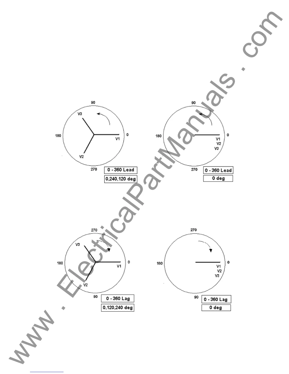
Screen, see 2.2.3.9. In the engineering world and in the following figures, the lagging diagram
displays negative rotation and will create negative sequence components, while the Lead and +/-
180 diagrams display positive rotation which is normal system activity.
Figure 19 Positive Phase Rotation Diagrams
Figure 20 Negative Sequence Phase Rotation Diagrams
29
www . ElectricalPartManuals . com
 Loading...