VM600 MPS quick start manual MAMPS-QS/E 1 - 13
Edition 2 - October 2018
Connecting power
INSTALLATION
1.4.1 Front panels
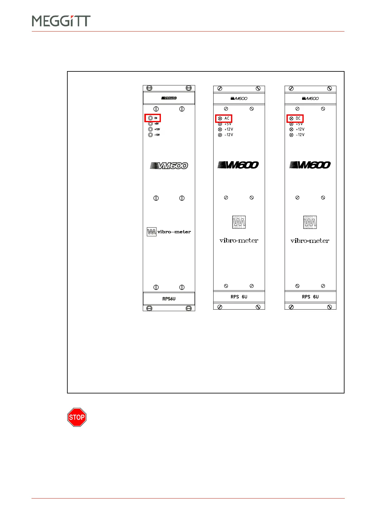
Figure 1-7 shows the panels of RPS6U rack power supplies with different inputs: AC or DC.
THE LATER VERSIONS OF THE RPS6U RACK POWER SUPPLY (330 W) CAN PROVIDE
SIGNIFICANTLY
MORE CURRENT COMPARED TO THE EARLIER VERSIONS OF THE
RPS6U RACK POWER SUPPLY (300 W), NOTABLY ON THE +5 V
DC
OUTPUT WHICH
CAN
BE UP TO 50 A (COMPARED TO THE PREVIOUS MAXIMUM OF 35 A).
A
CCORDINGLY, LATER VERSIONS OF THE RPS6U POWER SUPPLY (330 W,
PNR 200-582-
X00-02h OR LATER) SHOULD BE USED ONLY WITH LATER VERSIONS OF
THE
VM600 SYSTEM RACK (ABE040 PNR 204-040-100-015 OR LATER, ABE042
PNR 204-042-100-015
OR LATER), AS THESE RACKS HAVE BEEN IMPROVED IN
ORDER
TO SUPPORT THE HIGHER CURRENTS AVAILABLE FROM A 330 W RPS6U
POWER SUPPLY.
Figure 1-7: Front panels for the different versions of the RPS6U rack power supply
(a) Panel of later (higher-power)
version of the RPS6U rack
power supply
(b) Panels of earlier (original)
version of the RPS6U rack power supply:
AC-input version (left) and
DC-input version (right)
IN, AC or DC LED:
Green indicates that the
external mains supply is
present and is within the
normal range.
This LED is on when
the RPS6U is operating
normally.
+5V, +12V and −12V LEDs:
Yellow indicates that the
corresponding internal
supply voltage is being
generated and is within the
normal range.
These LEDs are on when
the RPS6U is operating
normally.
(AC-input version) (DC-input version)
 Loading...


