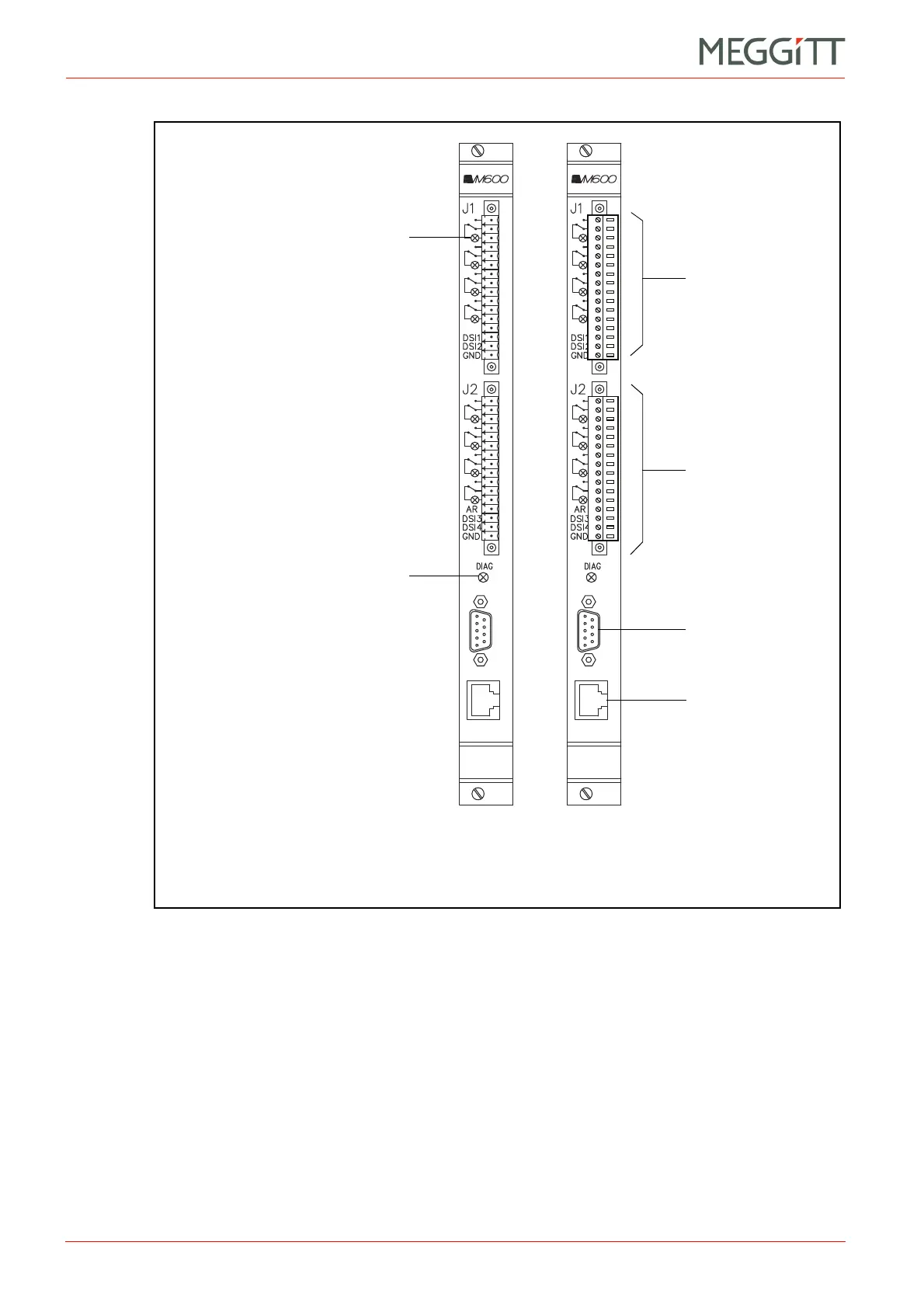
Connector J2
(Not used)
Connector J1
(a) (b)
RS-232 connector for
local configuration
DIAG indicator.
The colours of the LED have the following
significance:
* Green – The card is in the correct slot
* Red – Slot number mismatch or HW error.
(Same function as the SLOT ERROR LED
on other cards.)
Status indicator for relay 1.
The colours of the LED have the
following significance:
* Green – Result of the relay’s logic
equation is false
* Red – Result of the relay’s logic
equation is true
* Yellow blinking – Relay error.
Operation of status indicators for
relay 2 to relay 8 are as for relay 1.
 Loading...


