85-03-01109 FV42 Page 43
3.3 ELECTRICAL TECHNICAL REFERENCES
AC Power Requirements
WARNING: Label all wires prior to disconnection when servicing controls. Wiring errors can cause improper and dangerous
operation. Verify proper operation after servicing.
For normal operation, this appliance requires 120 VAC, 2 Amp power or a 6V DC power source. The AC
power supply to this Fireplace must be hot at all times and shall not have a switch installed in it.
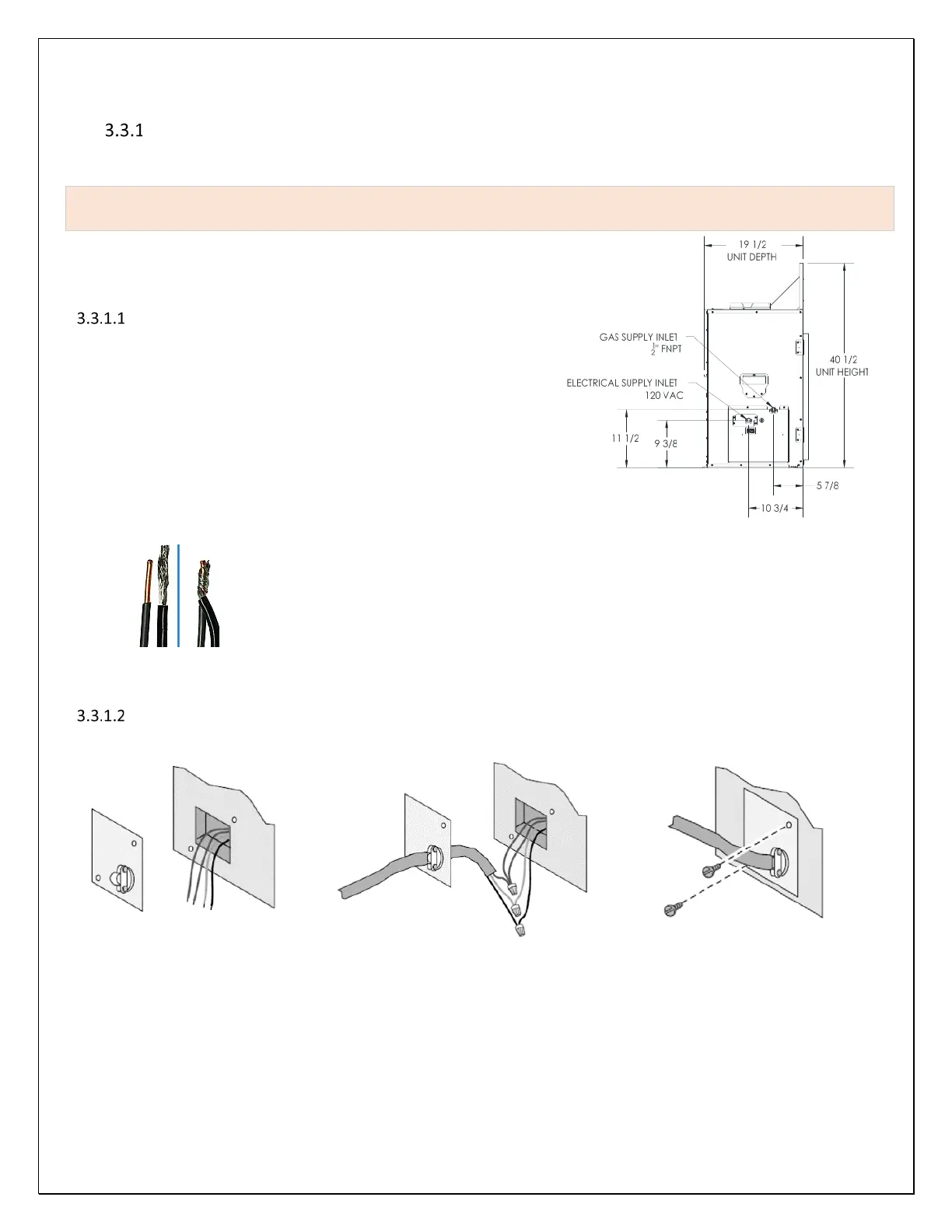
This appliance is equipped with an electrical junction box on the left
side. Backup DC power supply connector wire harness is supplied with
this fireplace and shall be installed adjacent to this appliance. See
Planning for AC Power Connection
On the left-side access box cover, you will find an electrical junction box
with a strain relief clamp. To connect AC power to this Fireplace, follow
these steps:
1. Remove the junction box cover plate (secured with two screws),
route the 3wire end of an extension cord or house power wire
cable through the strain relief in the cover plate.
2. Strip the ends of the house power wires and the three color
coded wires within the junction box. Connect each color-coded
wire to corresponding colored wires within the junction box. Use
the supplied wire nuts to connect each wire pair ends.
Note: When connecting two
braided wires using wire nuts, strip both braided wire ends at least ½” and twist the two
bare ends together before using wire nuts. When connecting a braided wire to a solid
copper wire, strip the solid copper wire end ½” and the braided wire end ¾”. Twist the
braided wire around the solid copper wire end before applying the wire nut.
3. Place connected wire ends within junction box then close and secure the junction box
cover plate.
AC Power Connection
Figure 3-25 Electrical Junction Box
Figure 3-26 Wire Connections