61
CC234
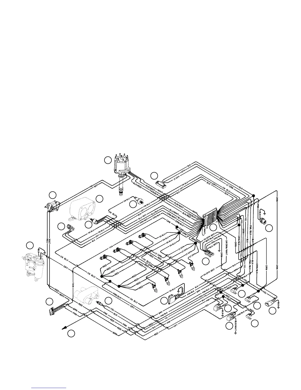
E.F.I. System Harness
74182
1 - Vapor Separator Tank (VST)
2 - Throttle Body
3 - Distributor
4 - Coil
5 - Electronic Spark Control (KS) Module
6 - Data Link Connector (DLC)
7 - Manifold Absolute Pressure (MAP) Sensor
8 - Knock Sensor
9 - Idle Air Control (IAC)
10 - Throttle Position (TP) Sensor
11 - Engine Coolant Temperature (ECT) Sensor
12 - Electronic Control Module (ECM)
13 - Fuel Pump Relay
14 - Ignition/System Relay
15 - Fuse (15 Amp) Fuel Pump
16 - Fuse (15 Amp) ECM/DLC/Battery
17 - Fuse (10 Amp) ECM/Injector/Ignition/Knock Module
18 - Harness Connector To Starting/Charging Harness
19 - Harness Connector To Lanyard Stop Switch (Optional)
20 - Harness Connector For Dual Engine Data Link Cable
21 - Positive (+) Power Wire To Engine Circuit Breaker
1
2
3
4
5
6
7
8
9
10
11
12
13
14
15
16
17
18
19
20
21
BLK = BLACK
BLU = BLUE
BRN = BROWN
GRN = GREEN
GRY = GRAY
ORN = ORANGE
PNK= PINK
PUR= PURPLE
RED= RED
TAN = TAN
WHT = WHITE
YEL = YELLOW
LIT = LIGHT
DRK= DARK
NOTE: All BLACK wires with a ground symbol are interconnected within the E.F.I. system harness.
NOTE: Component position and orientation shown above is arranged for visual clarity and ease of circuit identification.
GR
Y
 Loading...