INSTALLATION MANUAL
Page 50 of 77 90-864198020
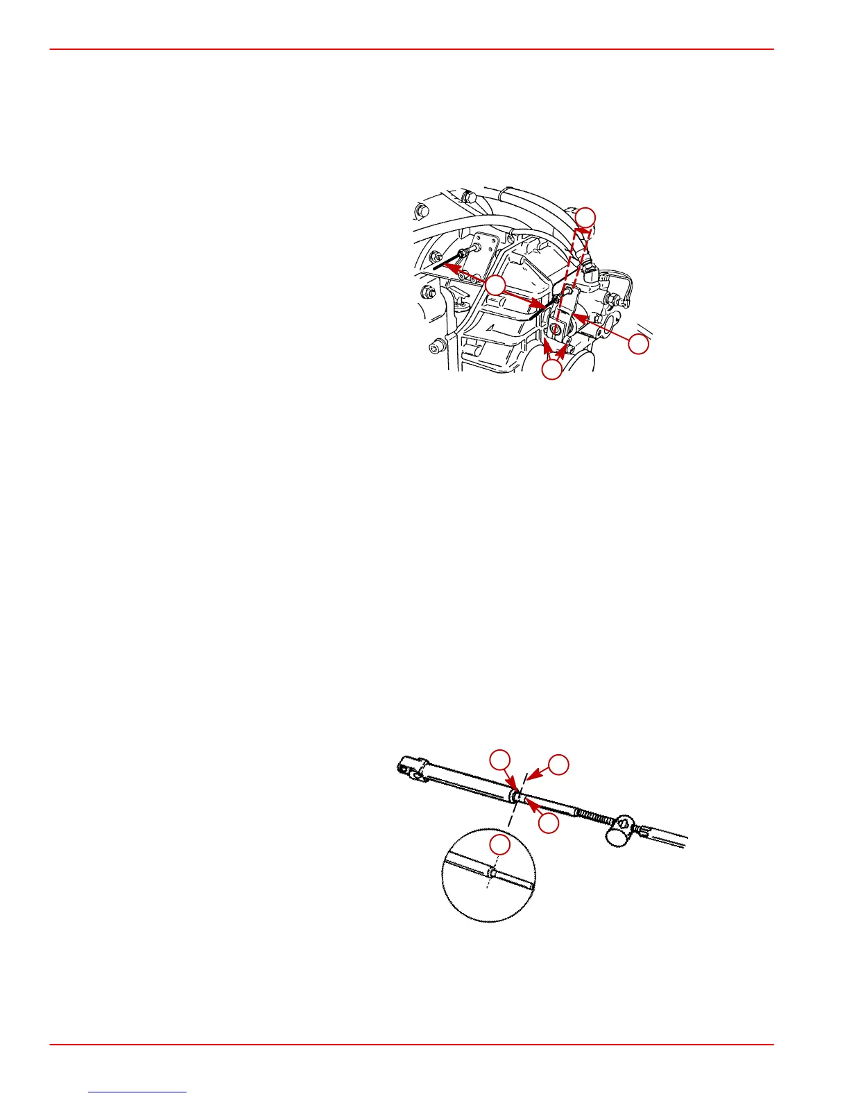
2. Check shift lever positioning as indicated:
IMPORTANT: Check that shift lever is positioned approximately 10 degrees aft of
vertical when in the NEUTRAL detent position and that the distance “c” between
studs in the following is set at 7-1/8 in. (181 mm). If necessary, loosen clamping bolt
and position lever so that dimension “c” is as shown when in the NEUTRAL detent
position and retighten bolt.
73587
a
b
d
c
Typical ZF / Hurth Transmission Shown
a-Shift Lever
b-Lever In NEUTRAL Detent 10 Degrees Aft Of Vertical
c-Dimension Between Studs - 7-1/8 in. (181 mm)
d-Clamping Bolt
3. Place remote control shift lever, and transmission shift lever, in NEUTRAL position.
4. Remove nuts and washers from shift cable attaching studs.
5. Locate center of remote control and control shift cable play (backlash), as follows:
a. Check that remote control is in NEUTRAL position.
b. Push in on control cable end with enough pressure to remove play, and mark
position “a” on tube.
c. Pull out on control cable end with enough pressure to remove play, and mark
position “b” on tube.
d. Measure distance between marks “a” and “b,” and mark position “c,” half-way
between marks “a” and “b.”
22024
a
b
c
c
6. Center cable-end play, then adjust cable barrel to align holes in barrel, and in cable end
guide, with attaching points on transmission.
 Loading...