D7.3L D-TRONIC DIESEL ENGINES - BRAVO MODELS
Page 53 of 90
NEUTRAL SAFETY SWITCH CONNECTION
1. Connect neutral safety switch wires at instrument panel and remote control. Refer to ap-
propriate wiring diagram. Secure connections as shown and coat with Liquid Neoprene.
Slide rubber sleeve over connections.
YEL/RED
YEL/RED
RED 36BC2
PUR 36BC3
PUR 36BC1
PUR 36BC
a
b
a
c
c
d
a-Instrument Harness Wires
b-Two Wire Connector
c-To Remote Control
d-Rubber Sleeves
TRIM POSITION SENDER CONNECTION
1. Connect trim position sender leads from gimbal housing to leads from engine harness.
24841
BLK
BLK
a
b
YEL 107
BLK GND3
a-From Engine Harness
b-From Gimbal Housing
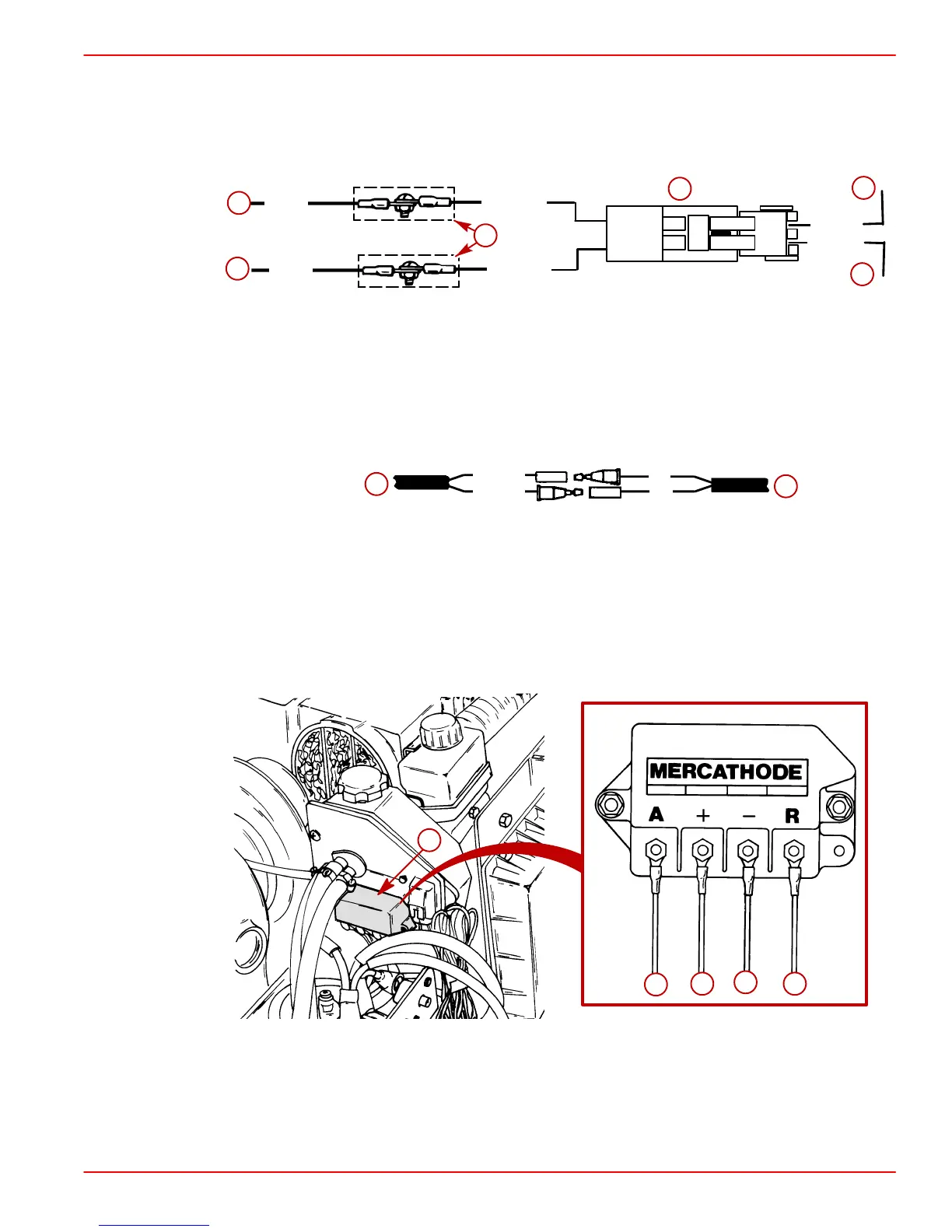
MERCATHODE CONTROLLER
1. Connect electrical leads to controller assembly.
2. Apply a thin coat of Liquid Neoprene to ALL electrical connections.
75955
a
22232
b
c
d
e
a-Controller Assembly Location
b-ORANGE Wire - From Electrode on Transom Assembly
c-RED/PURPLE Wire - Connect (Other End) to Positive (+) Battery Terminal
d-BLACK Wire - From Engine Harness
e-BROWN Wire - From Electrode on Transom Assembly
 Loading...


