D7.3L D-TRONIC DIESEL ENGINES - BRAVO MODELS
Page 8 of 90
Installation Requirements
Boat Construction
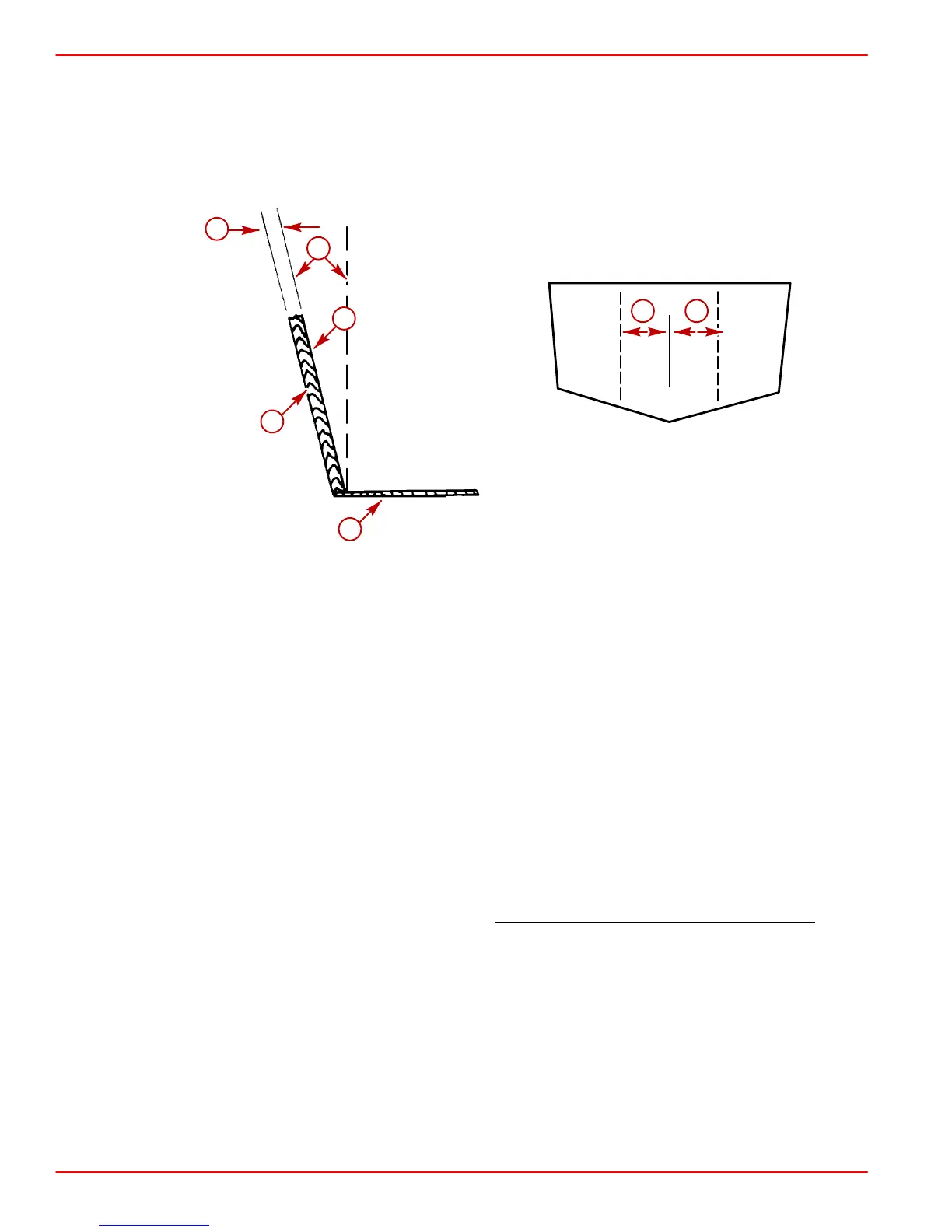
TRANSOM
22170
22033
b
c
f
a
d
e e
a-Transom Thickness - 2 in. (51mm) Minimum to 2-1/4 in.(57mm) Maximum
b-Inner Surface of Transom Must Be Parallel Within 1/8 in. (3mm) in Area
Covered by Transom Plate (e) and Remain Within Transom Thickness Limits.
c-Outer Surface of Transom Must Be Parallel Within 1/16 in. (2 mm) in Area
Covered by Transom Plate (e) and Remain Within Transom Thickness Limits.
d-Remove Keel (if Equipped) 4 ft. (1.2m) Forward to Transom
e-Transom Plate Covers 8 in. (203 mm) to either side of the vertical centerline
f-Transom Angle - 10 Degrees to 16 Degrees
ENGINE BED
Distance between starboard and port engine mount is 22-1/2 in. (572mm). Engine bed must
position engine so that a minimum of 1/4 in. (6mm) up and down adjustment still exists on
mounts after performing final engine alignment. This is necessary to allow for realigning en-
gine in the future.
NOTE: Although the engine mounts allow some adjustment, it is a good practice to insure
that the front and rear mount locations in the vessel are in parallel planes. This may be
checked by tying a string from the left front mount location to the right rear mount location
and another from right front to left rear. The strings should touch where they cross
.
 Loading...


