73371
BLK = BLACK
BLU = BLUE
BRN = BROWN
GRY = GRAY
GRN = GREEN
ORN = ORANGE
PNK = PINK
PUR = PURPLE
RED = RED
TAN = TAN
WHT = WHITE
YEL = YELLOW
LIT = LIGHT
DRK = DARK
j
a
b
c
d
e
f
h
i
g
GASOLINE ENGINES SKI MODELS
Page 41 of 48
Quicksilver Instrumentation Wiring Diagrams
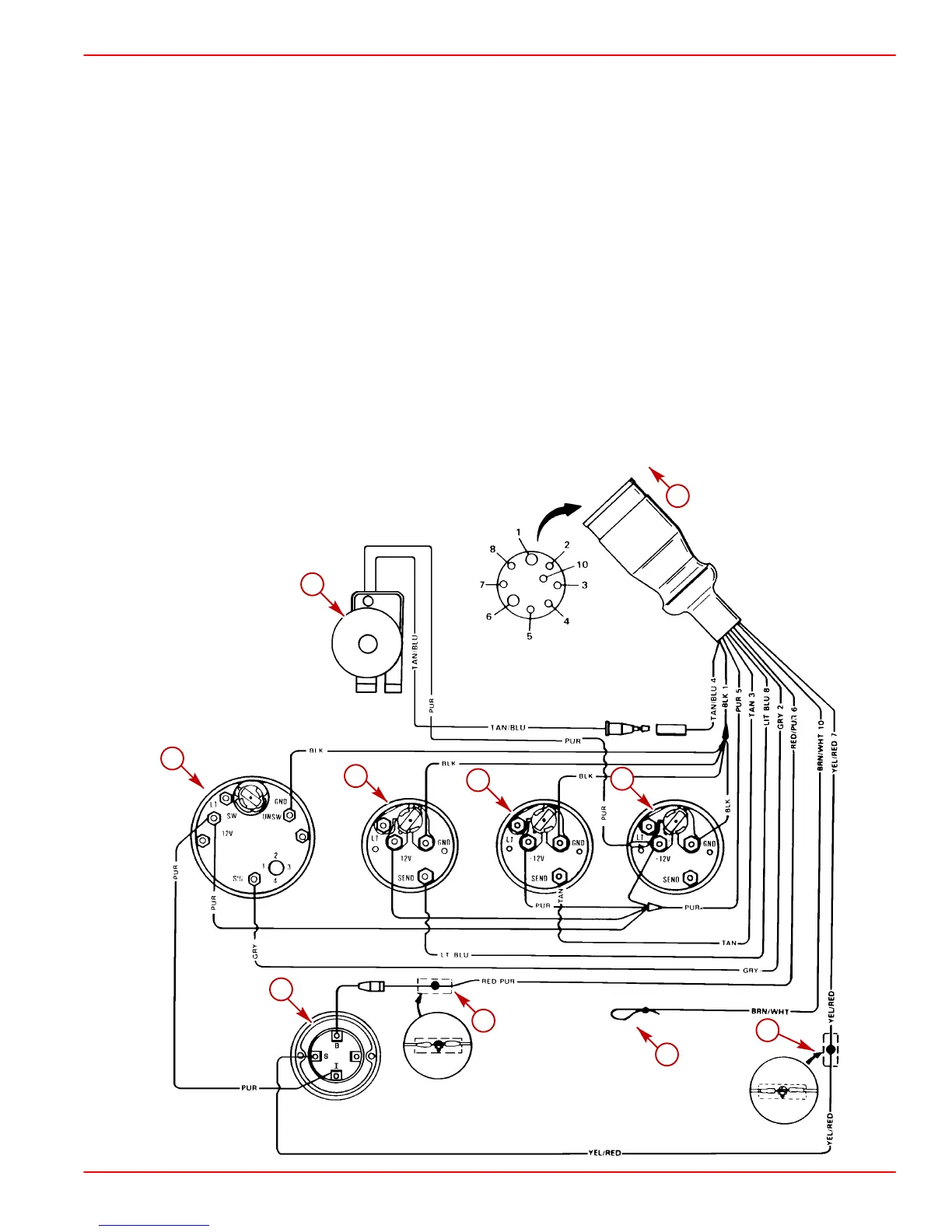
MIE Gasoline Engine - Typical Single Station Installation
Refer to gauge manufacturer’s instructions for specific connections.
NOTE 1. Connect Wires Together with Screw and Hex Nut; Apply Liquid Neoprene to Connection and Slide Rubber
Sleeve over Connection.
NOTE 2. Power for a Fused Accessory Panel May Be Taken from This Connection. Load Must Not Exceed 40 Amps.
Panel Ground Wire Must Be Connected to Instrument Terminal That Has an 8-Gauge BLACK (Ground) Harness
Wire Connected to it.
NOTE 3. Taped back BROWN-WHITE wire may be used for an accessory. LOAD MUST NOT EXCEED 5 AMPS.
a-Audio Warning horn
b-Tachometer
c-Oil Pressure
d-Water Temperature
e-Battery Meter
f-Ignition Switch
g-Read/Observe NOTE 1
h-Read/Observe NOTE 1 and 2
i-Read/Observe NOTE 3
j-To Engine Wiring Harness
 Loading...