27
The steps below can be used to collect feature measurements for NLEC import;
• Position the NLEC calibration artifact to be used on the measuring stage, ensuring approximate
alignment of the grid to the travel of the X and Y axis.
• Measure a feature at each end of the bottom row of features on your calibration artifact and
execute a “skew” alignment between the features. You can also directly probe a skew feature
along the artifact.
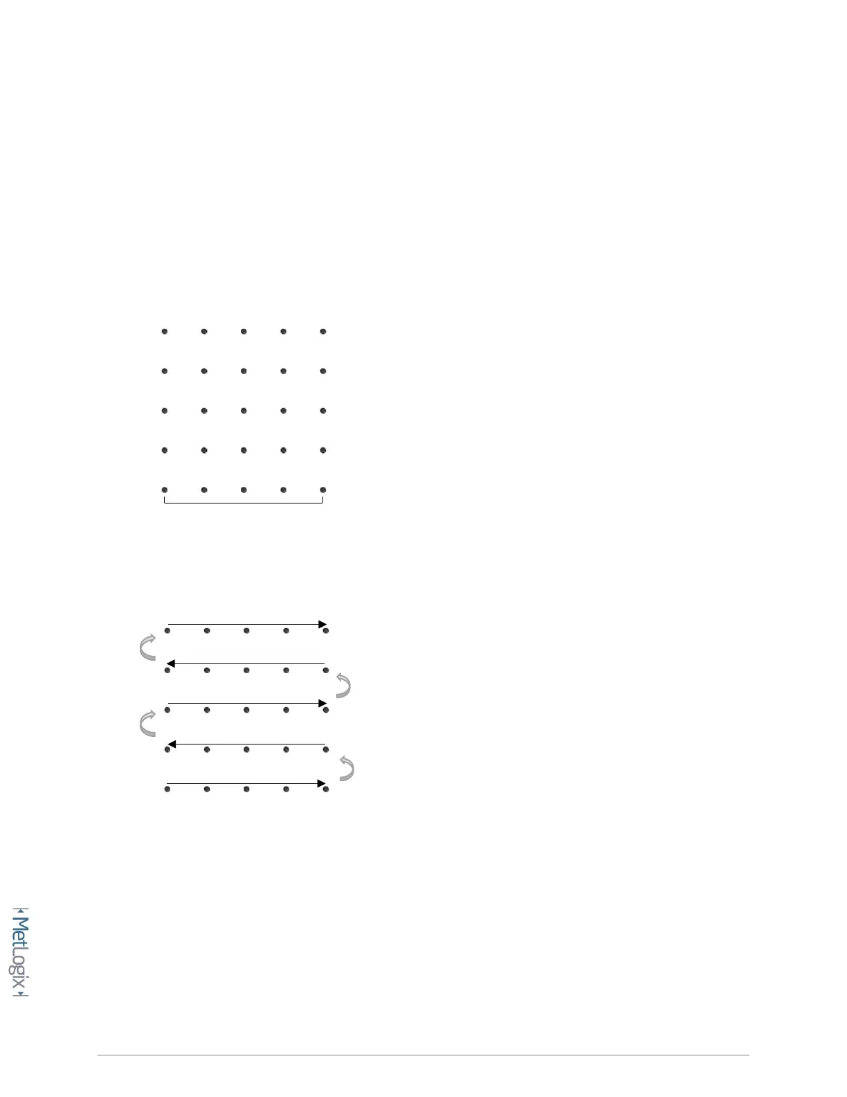
• Zero the X and Y position of the feature at the bottom left corner of your calibration grid.
• The established skew and zero should appear as follows;
• Delete the skew and circle features from the feature list, and then proceed to measure all of the
grid features in serpentine order starting from the bottom left, as seen below;
• Using the Mx200 tolerancing screens, set the nominal(or certified) X and Y position for each
feature in your grid, starting with (0,0).
• Navigate to the NLEC correction setup page.
Mx Button-->Setup-->Error corrections-->NLEC.
• Press the Import softkey to import your NLEC features.
• After the “NLEC Import Successful” message the correction should become enabled
automatically.
0,0
Skew
Start