18
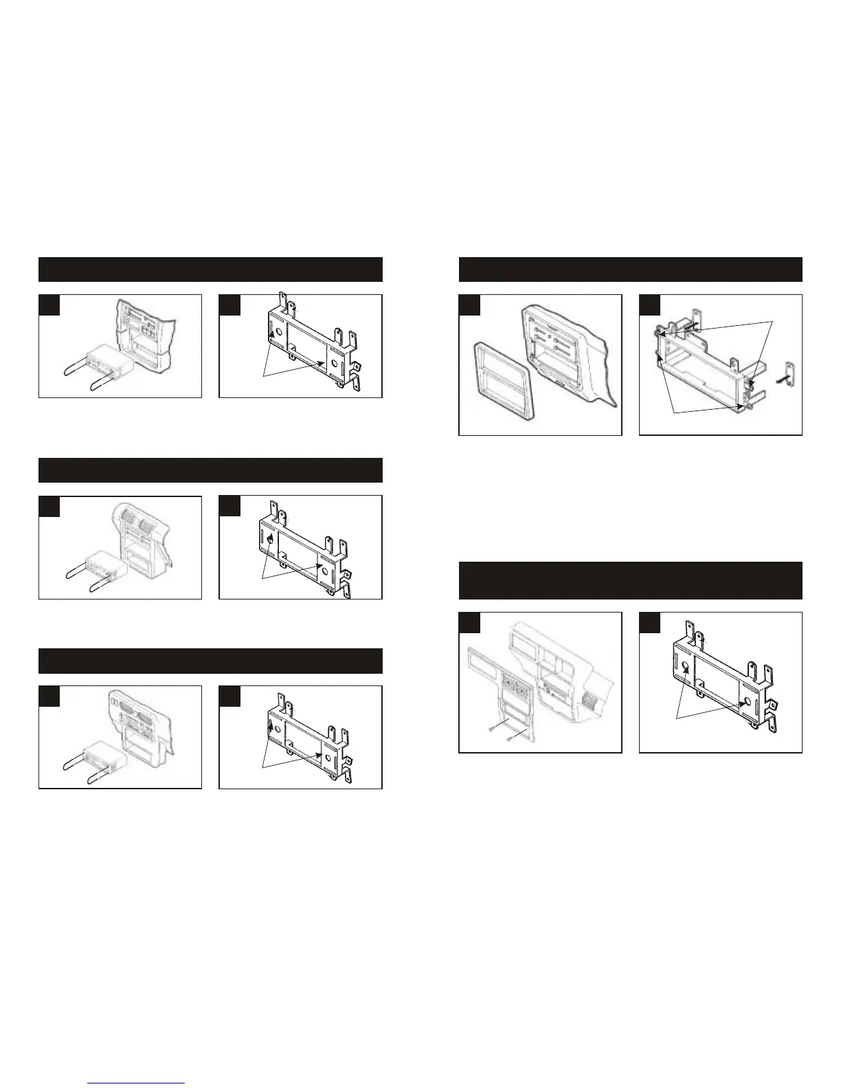
3
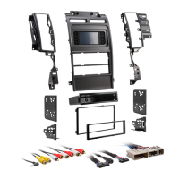
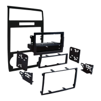
Disconnect the negative battery terminal to
prevent an accidental short circuit. Remove
the ashtray and (2) screws exposed in the
ashtray cavity. Using Metra's 86-5618, pull
the factory head unit from the dash and
disconnect the wiring.
1
FORD Bronco II 1989-90 / Explorer 1991-94 / Ranger 1989-94
MAZDA Navajo 1991-94 / B-Series Pickup 1994
2
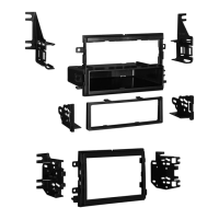
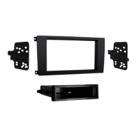
Disconnect the negative battery terminal to
prevent an accidental short circuit. Carefully
pull and remove the dash trim bezel.
Remove (4) screws securing the factory
head unit and disconnect the wiring.
1
FORD Bronco (full size) / F-Series Pickup 1987-91
2
1
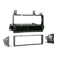
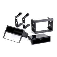
MAZDA MX3 1992-96
2
Disconnect the negative battery terminal to
prevent an accidental short circuit. Unsnap
the side trim pieces from the factory head
unit. Using Metra's 86-5618, pull the unit
from the dash and disconnect the wiring.
1
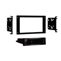
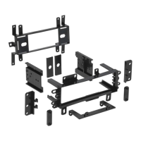
MAZDA MPV 1996-99
2
Disconnect the negative battery terminal to
prevent an accidental short circuit. Using
Metra's 86-5618, pull the factory head unit
from the dash and disconnect the wiring.
1
MAZDA MX6 1993-97 / 626 1993-00
2
Disconnect the negative battery terminal to
prevent an accidental short circuit. Using
Metra's 86-5618, pull the factory head unit
from the dash and disconnect the wiring.
Cut and remove the shaft supports from the
Faceplate. Skip to step #3c in the
Installation Instructions for ALL VEHICLES
on Page #22.
Cut and remove the shaft supports from the
Faceplate. Skip to step #3c in the
Installation Instructions for ALL VEHICLES
on Page #22.
Cut and remove the shaft supports from the
Faceplate. Skip to step #3c in the
Installation Instructions for ALL VEHICLES
on Page #22.
Cut and remove the shaft supports from the
Faceplate. Skip to step #3c in the
Installation Instructions for ALL VEHICLES
on Page #22.
"F"
"D"
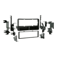
Cut and remove all mounting tabs on Radio
Housing #2 EXCEPT tabs "D" and "F".
The mounting tabs can be identified by the
stamped letter on the back of each tab.
Locate Spacer Set #1. (The Spacers must
be placed behind the mounting tabs during
installation in step #5). Skip to the
Installation Instructions for ALL VEHICLES
on Page #21.
 Loading...