EasyManua.ls Logo

Metra Electronics 99-5722 User Manual

Metra Electronics 99-5722
16 pages
To Next Page IconTo Next Page
Page #1 background imageLoading...
Page #1 background image
CAUTION!
All accessories, switches, climate
controls panels, and especially air bag indicator
lights must be connected before cycling the
ignition. Also, do not remove the factory radio
with the key in the on position, or while the
vehicle is running.
INSTALLATION INSTRUCTIONS
99-5722
The World’s best kits.
®
KIT FEATURES
DIN radio provision with pocket
ISO DIN radio provision with pocket
ISO DDIN radio provision
Painted silver
Touchscreen display for climate and personalization features
KIT COMPONENTS
• A) Radio trim panel with touchscreen display • B) A/C vent trim panels • C) ISO DDIN brackets • D) ISO DDIN trim plate • E) ISO DIN brackets
• F) ISO DIN trim plate • G) Pocket • H) (10) #8 x 3/8” Phillips screws
TOOLS REQUIRED
• Panel removal tool • Phillips screwdriver
• 9/32” socket wrench • Cutting tool
TABLE OF CONTENTS
Dash Disassembly ...............................................2-3
Kit Preparation .......................................................4
Kit Assembly
–DIN radio provision with pocket ........................5
–ISO DIN radio provision with pocket ..................6
–ISO DDIN radio provision .....................................7
Axxess Interface Installation ............................8-16
WIRING & ANTENNA CONNECTIONS
(sold separately)
Wiring Harness: Axxess interface
and harness included
Antenna Adapter: 40-EU10 (sold separately)
A B C
G
D E F
Ford Taurus* 2010-2012
H
* Only for models with a key start
Question and Answer IconNeed help?

Do you have a question about the Metra Electronics 99-5722 and is the answer not in the manual?

Metra Electronics 99-5722 Specifications

General IconGeneral
BrandMetra Electronics
Model99-5722
Installation TypeDash Kit
ColorBlack
ISO DDIN Radio ProvisionYes
Painted to match factory colorYes
Wiring HarnessNot included
Antenna AdapterNot included
ApplicationsFor installing an aftermarket radio
FunctionDash Kit

Summary

Kit Overview and Components

Kit Features

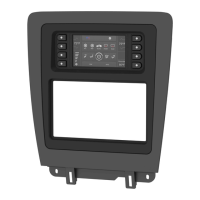
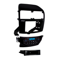
Lists the capabilities and design of the new radio kit.

Kit Components

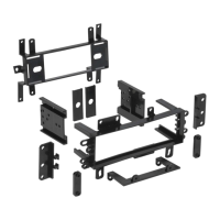
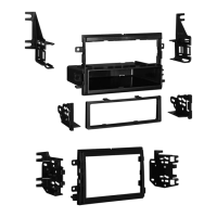
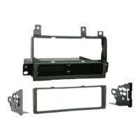
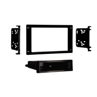
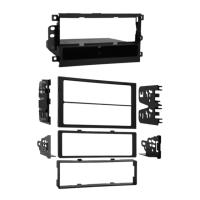
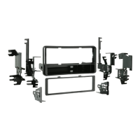
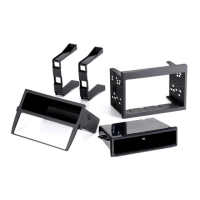
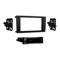
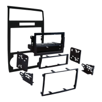
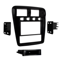
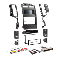
Identifies all parts included in the installation kit.

Required Tools

Lists essential tools for the installation process.

Wiring and Antenna Connections

Details necessary connection accessories for the installation.

Dash Disassembly

Center Console and Steering Column Trim Removal

Covers removal of console panels, knee bolster, and steering column trim.

Instrument Panel and Center Stack Trim Removal

Focuses on gauge cluster, radio/climate area, cup holder, and shifter trim.

Radio, Display Screen, and Chassis Removal

Details removal of the main radio/climate panel, display screen, and radio chassis.

Kit Preparation

Prepare Factory Radio/Climate Control Panel

Instructions for removing vents and trim from the original panel.

Assemble 99-5722 Radio/Display Trim Panel

Securing A/C vent panels to the new trim panel using screws.

Kit Assembly

DIN Radio Provision with Pocket Installation

Steps to install a single DIN radio with a pocket.

ISO DIN Radio Provision with Pocket Installation

Steps for installing a single DIN radio using ISO brackets and a pocket.

ISO DDIN Radio Provision Installation

Instructions for installing a double DIN radio with specific brackets.

Axxess Interface Installation

Interface Features

Lists the functionalities provided by the Axxess interface.

Interface Components

Identifies the parts included in the Axxess interface package.

Wiring Connections

Non-Amplified System Wiring

Connects 16-pin and 5722 harnesses for non-amplified vehicles.

Steering Wheel Control Integration

Connects steering wheel controls for various radio brands.

Backup Camera Connection

Instructions for adding an aftermarket backup camera.

Amplified System Wiring

Connects 16-pin and 5722 harnesses for amplified vehicles.

Installing the Interface

Connect 5722 Harness to Display

Connects the main 5722 harness to the touchscreen display ports.

Connect 4-Pin Harness to Display

Connects the 4-pin harness with yellow RCA jacks to the display.

Interface Operation and Configuration

Initializing the Interface

Steps to turn on and test the interface after installation.

Final Assembly of Dash Components

Reassembly of the vehicle's dashboard in reverse order.

SYNC Feature Usage

Instructions on how to use the SYNC feature with the new interface.

Touchscreen Display Controls

Overview of the HVAC controls and menu navigation on the touchscreen.

Touchscreen Display Settings

Configuration Settings Menu

Accessing and adjusting settings like backlight, backup camera, and SWC.

Steering Wheel Control Customization

Remapping or dual-assigning steering wheel control buttons.

Touchscreen Calibration

Process for calibrating the touchscreen sensitivity.

Steering Wheel Control Settings

Radio Selection for SWC

Choosing the correct radio type for steering wheel control compatibility.

Button Remapping and Dual Assignment

Customizing steering wheel button functions.

Related product manuals