4.3 Energy Test
1. Select a suitable energy range using the mode switch.
• Use the HIGH range for normal adult testing.
• Use the LOW range for low energy testing, where the en-
ergy does not exceed 50 Joule and the peak voltage does
not exceed 1200 volts.
2. Securely place the defibrillator paddles on the QA-45 contact
plates, and discharge the defibrillator. The APEX (+) pad
should be connected to the right-hand plate, and the STERNUM
pad to the left plate. This ensures correct signal polarity for the
oscilloscope output. A reversal of this configuration will not
damage the QA-45, nor will it give incorrect energy readings.
However, the polarity of the oscilloscope output will simply be
reversed. The discharge from the defibrillator is transferred to
the QA-45's load resistance.
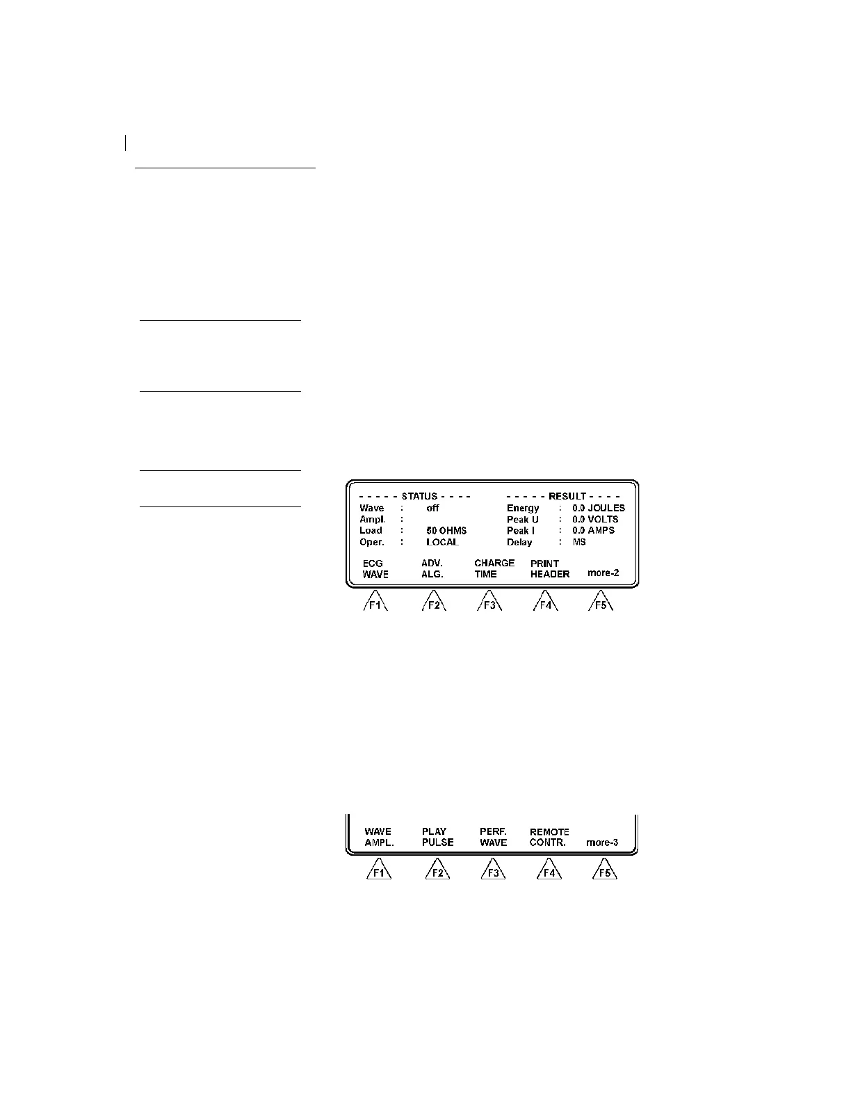
3. QA-45 calculates the energy delivered over the load resistance
and displays the result in joules under RESULT. See below:
QA-45 also shows the energy measured, the maximum voltage
and the maximum current in the energy wave. Following the
discharge from the defibrillator, QA-45 shows a playback of the
wave from the ECG output. A new pulse can be generated when
the LCD display shows 'LOCAL'.
4. Following a discharge from the defibrillator, the instrument
shows a playback of the wave from the ECG output. The dis-
play will thus be in playback mode. When this is shown in one
line, QA-45 automatically prints out the result.
5. The discharged pulse can be repeated. To do this press more-2
(F5) to advance to page 2 of the main menu.
Press PLAY PULSE (F2). The display will show 'Oper: Play-
back,' and displays the result in joules under RESULT.
APEX (+) pad → right plate
STERNUM pad → left plate
Note
If the maximum voltage for a se-
lected range is exceeded, the LCD
display will show ‘WARNING!
Overload’
3