6. Control and Calibration
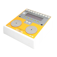
This chapter explains the QA-45 maintenance procedures, including
testing and calibration.
6.1 Required Test
Equipment
• Digital multimeter, 10 uV resolution, 0.1% accuracy.
• Frequency counter
• Oscilloscope
• Variable VIA power supply
• 10 V (+0.01 v) power source
• Pulse generator: square pulse, 10 ms width, 10V amplitude, 80
pulses per. minutes (for pacer module).
6.2 Preparation
Set the switches on QA-45 to the following positions:
Mode: Low
Power: Off
Connect a power supply to the battery eliminator input on QA-45.
Adjust the power supply to 9V (±0.2v) with a power limitation of
200 mA (±50 mA).
6.3 References
The function keys are numbered 1 to 5, with switch 1 farthest to left.
6.4 Test
1. Set power to ON. Wait 3 seconds, and measure the current from
the power supply. Requirement: 68 mA (±5 mA).
2. Adjust P2 on the processor board to obtain the best possible con-
trast on the display. The display should show the main menu
and the result with 0-data. Press function switch 5 and check
that QA-45 changes between various menus. Adjust P103 out of
limit.
3. Set power to OFF, and then back to ON after about 1 second.
The display should show the software version number for a
brief period, before showing the main active display. (By test
under production a additional item shall be used.)
4. Measure the operating voltages in QA-45 with the multimeter.
The following values are acceptable:
Test point
- +
Level Maximum
Deviation
1

 Loading...