4 Jamesbury 3-Piece Ball Valves, Series 4000, Threaded End, Socket Weld, Butt Weld, Rev 2.0, Safety Manual
3.2 Environmental and application restrictions
Ensure that the valve is selected and specied correctly for the application and that the process conditions and
atmospheric conditions are taken into account. Environmental limits for which the product is designed and
general instructions for applications are given in the product IMO and technical bulletin. Please contact Metso
in case more details are needed. Proper specication of application, process and environmental conditions is
the user responsibility.
The reliability values given in Paragraph 3.5 assume the valve is selected correctly for the service and that all
the environmental and application restrictions are considered. If the valve is used outside of its application or
environmental limits, or with incompatible materials, the reliability information shown in Paragraph 3.5 may
not be valid.
3.3 Useful lifetime
The useful lifetime needed for functional safety reliability estimations is typically 10 – 15 years for the Series
4000 3-piece ball valves, if Proof test (5.1), Partial Stroke test (5.2), Maintenance (5.3), have been considered
accordingly. The “useful lifetime” is the time period after burn-in and before wear-out, when the failure rate of
a simple item is more or less constant. Note that the design life of the valve is higher, and should not be con-
fused with “useful lifetime” used in these reliability evaluations.
3.4 Connecting the 3-piece ball valve to a safety system
The complete nal element (valve-actuator-accessories assembly) is connected to the safety system through an
electrical connection, which commonly operates an intelligent partial stroke device or a solenoid valve (see Fig 1).
A single nal element installation provides hardware fault tolerance (HFT) equal to 0. If HFT equal to one is re-
quired, then two nal elements installed in series (block) or parallel (vent) must be used.
Note, that the single nal element may contain internal redundancy of some accessories, e.g. where 1oo2 or 2oo2
solenoid valves are required.
Note that the bare shaft valve cannot be connected to the safety system directly.
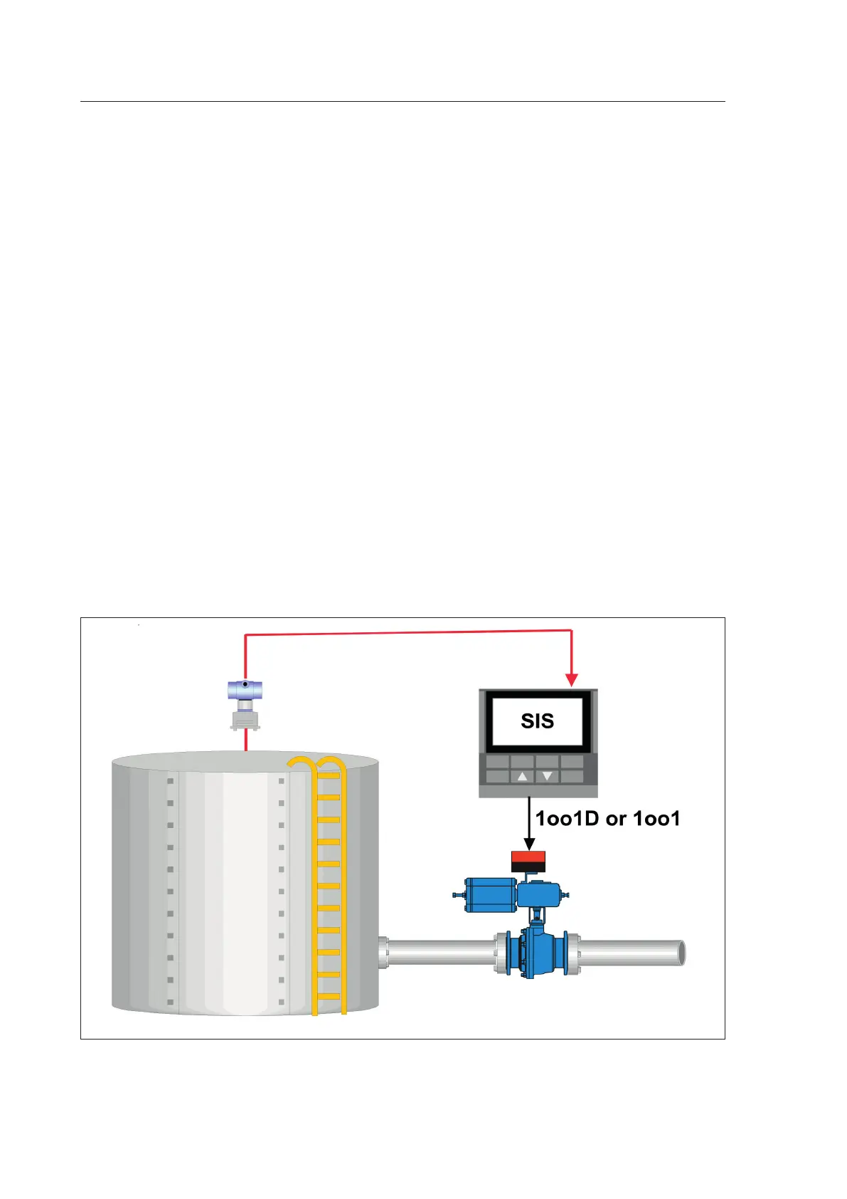
Figure1. Schematic picture of a safety loop.
The nal element with spring return actuator is connected to the Safety Instrumented System (SIS) via a sole-
noid or safety valve controller (partial stroke device). This shows a single channel nal element subsystem with
voting, either 1oo1D or 1oo1.

 Loading...