IMO 11/19
IMO-553 EN 9
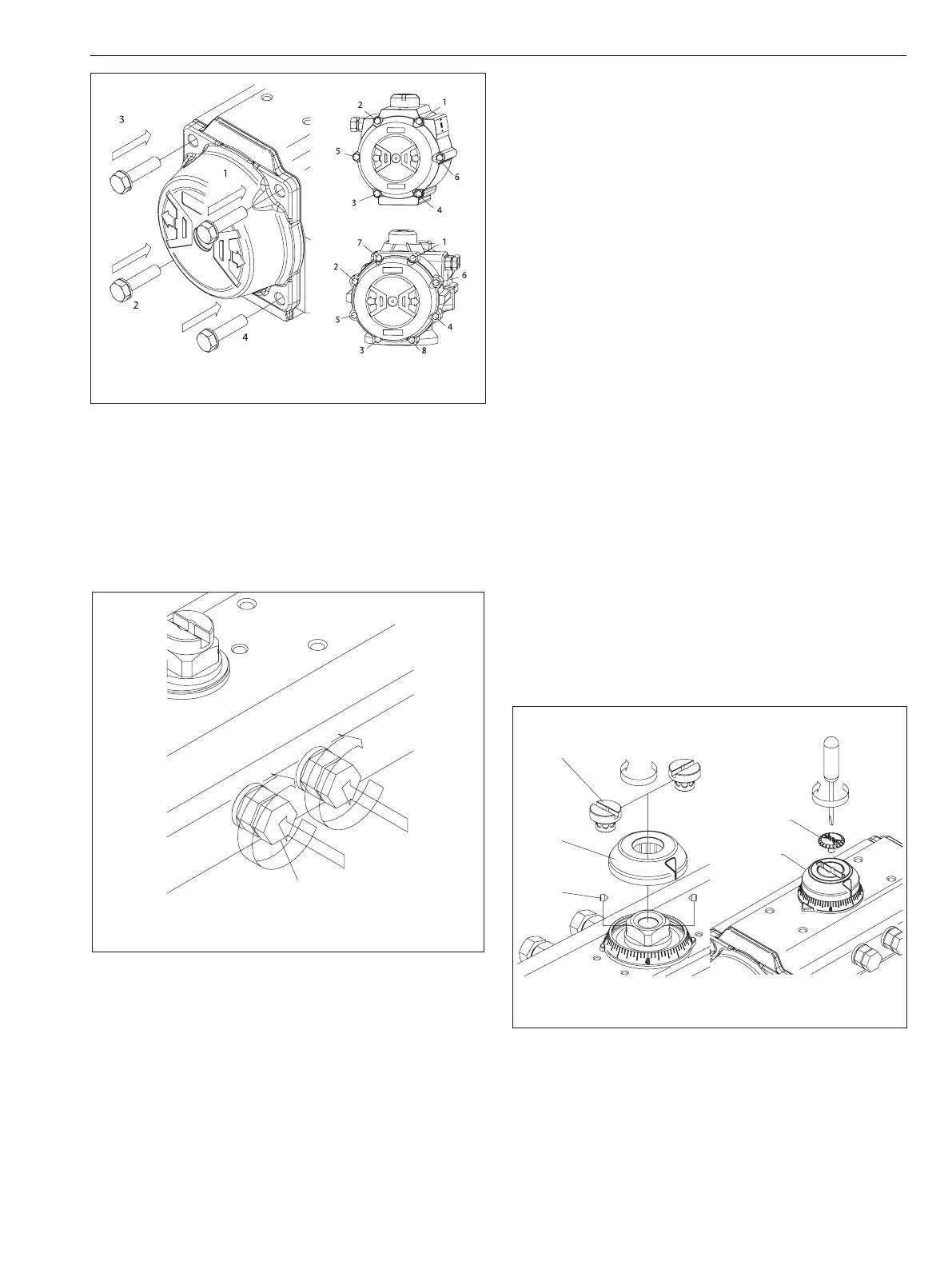
4. Assembly of Stop Screws (2) and Stroke
Adjustment. (Figure 17):
A. Insert the nut (4), washer (3), and o-ring (11) onto the
stop screws (2).
B. Screw the stop screws (2) into the body (50).
5. External Travel Stop Adjustment, (Figure 17):
2, 4, 3 and 11
Figure 17
The stop adjustment screw (2) to the right controls the
clockwise end of travel. The stop adjustment screw (2) to
the left controls the counter-clockwise end of travel.
A. Cycle the actuator/valve to the clockwise end of
travel and measure to determine if the valve is in
the proper position. (In most applications this will be
fully closed.)
B. If the valve is not in the correct clockwise position,
turn the right stop adjustment screw (2) IN to reduce
actuator travel, or OUT to increase actuator travel.
C. When the correct clockwise position is obtained, hold
the adjusting screw (2) stationary while tightening
the lock nut (4).
D. Cycle the actuator/valve to the counter-clockwise
end of travel and measure to determine if the valve is
in the proper position. (In most applications this will
be fully opened.)
E. If the valve is not in the correct counter-clockwise
position, turn the left stop adjustment screw (2)
IN to reduce actuator travel, or OUT to increase
actuator travel.
F. When the correct counter-clockwise position is
obtained, hold the adjusting screw (2) stationary
while tightening the lock nut (4).
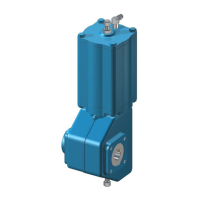
6. Position Indicator (19, 39) Assembly. (Figure 18):
A. Fit position indicator (19) on the shaft (60), verifying
that it indicates the correct actuator position.
B. Tighten cap screw (39) to secure the position
indicator.
7. Setting 100% Adjustable Stop (If applicable).
(Figure 19):
To limit the rotation on the stroke beyond the standard ±5°
of a VPVL actuator, a stainless steel 100% adjustable travel
stop option can be added. The stops, located in the end caps,
allow the valve position to be set anywhere between full
closed and full open. This option limits travel of only the
counter-clockwise stroke for standard double-acting and
spring-closed units. Follow the proceeding steps in order to
set the 100% adjustable travel stops.
19.5
19.1
19.6
19
39
Figure 18
Figure 16

 Loading...