19
CHAPTER 3: AMPLIFICATION AND AUDIO
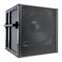
The 750-LFC loudspeaker’s driver is powered by a proprietary
two-channel, open-loop, class D amplifier. The audio signal is
processed with correction filters for flat phase and frequency
response, and by driver protection circuitry. Each channel has
peak and rms limiters that prevent driver over-excursion and
regulate voice coil temperatures.
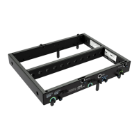
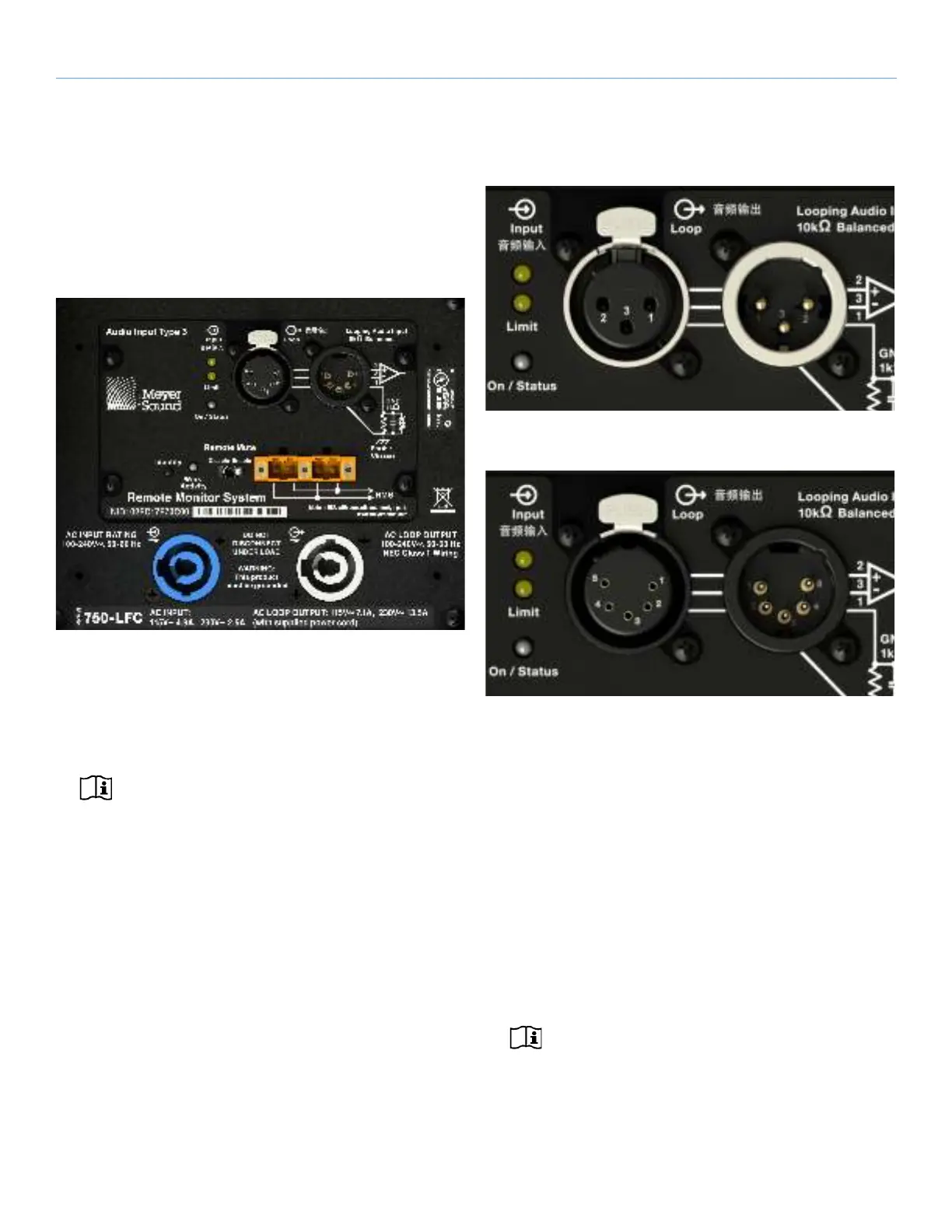
The 750-LFC user panel includes Input and Loop output
connectors for audio, Limit and On/Status LEDs, and RMS
connectors and controls (see Chapter 5, “RMS Remote
Monitoring System”).
NOTE: The RMS capability is optional, so if it is
desired, please specify this feature when placing
an order.
AUDIO CONNECTORS
The 750-LFC is available with XLR 3-pin (Figure 12) or 5-pin
(Figure 13) connectors for audio Input and audio Loop output.
XLR 5-pin connectors accommodate both balanced audio and
RMS signals.
Audio Input (XLR 3-Pin or 5-Pin Female)
The XLR 3-pin or 5-pin female input connector accepts
balanced audio signals with an input impedance of 10 kΩ. The
connector uses the following wiring scheme:
•Pin 1 — 1 kΩ to chassis and earth ground (ESD clamped)
•Pin 2 — Signal (+)
•Pin 3 — Signal (–)
•Pin 4 — RMS (polarity insensitive)
•Pin 5 — RMS (polarity insensitive)
•Case — Earth (AC) ground and chassis
NOTE: Pins 4 and 5 (RMS) are included only with
XLR 5-pin connectors.
Figure 11: 750-LFC User Panel (XLR 5-pin version)
Figure 12: XLR 3-Pin Audio Connectors, Input and Loop Output
Figure 13: XLR 5-Pin Audio Connectors, Input and Loop Output
 Loading...