43
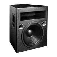
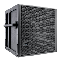
APPENDIX B: 750-LFC SPECIFICATIONS
Loudspeaker system predictions for coverage and SPL are available in Meyer Sound’s MAPP prediction software, which can be
found on the Meyer Sound website:
meyersound.com/products
.
ACOUSTICAL
Operating Frequency Range35 Hz – 125 Hz
Note: Recommended maximum operating frequency range.
Response depends on loading conditions and room acoustics.
Frequency Response37 – 110 Hz (±4 dB)
Note: Measured in half-space with pink noise at 4 m, 1/3-octave frequency resolution.
Phase Response43 Hz – 110 Hz ±30 degrees
Linear Peak SPL130.5 dB with crest factor >9 dB (M-noise), 130.5 dB (Pink-Noise), 132 dB (B-Noise)
Note: Linear Peak SPL is measured in half-space at 4 m referred to 1 m.
Loudspeaker SPL compression measured at the onset of limiting, 2-hour duration, and
50° C ambient temperature is <2 dB.
M-noise is a full bandwidth, (10Hz–22.5kHz) test signal developed by Meyer Sound to
better measure the loudspeaker’s music performance. It has a constant instantaneous
peak level in octave bands, a crest factor that increases with frequency, and a full band-
width Peak to RMS ratio of 18 dB. The presence of a greater-than (>) symbol with regard
to crest factor indicates it may be higher depending on EQ and boundary loading.
Pink noise is a full bandwidth test signal with a peak-to-RMS ratio of 12.5 dB.
B-noise is a Meyer Sound test signal that ensures measurements reflect system behavior
when reproducing the most common input spectrum, and verify there is still headroom
over pink noise.
COVERAGE
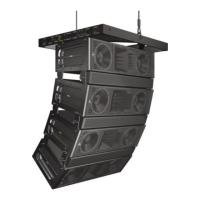
360° (single unit); varies with number of units and configuration
TRANSDUCERS
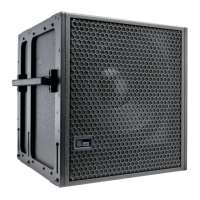
Low FrequencyOne 15-inch dual-coil, long-excursion cone driver; 2 Ω nominal impedance
AUDIO INPUT
TypeDifferential, electronically balanced
Maximum Common Mode Range±15 V DC, clamped to earth for voltage transient protection
ConnectorsXLR 3-pin female with male loop; Optional 5-pin connectors to accommodate both bal-
anced audio and RMS signals
Input Impedance10 kΩ differential between pins 2 and 3
WiringPin 1: Chassis/earth through 1 kΩ, 1000 pF, 15 V clamped network to provide virtual
ground lift at audio frequencies
Pin 2: Signal (+)
Pin 3: Signal (–)
Pin 4: RMS (polarity insensitive)
Pin 5: RMS (polarity insensitive)
Case: Earth ground and chassis
Note: Pins 4 and 5 (RMS) included only with XLR 5-pin connectors.
Nominal Input Sensitivity6.0 dBV (2.0 V rms) continuous is typically the onset of limiting for noise and music
Input LevelAudio source must be capable of producing +20 dBV (10 V rms) into 600 Ω to produce
the maximum peak SPL over the operating bandwidth of the loudspeaker
 Loading...