RMS USER GUIDE
31
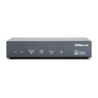
module standoff), remove the paint with a Dremel
®
tool
or sandpaper. Make sure to remove all debris from the
chassis before proceeding.
CAUTION: Do not grind down the metal
around the screw hole too much. If the metal is
too thin it will reduce the metal-to-metal contact (and
grounding) with the HP/MP RMS module.
6. Remove the plastic connector on the power supply
board (next to the fan power connector).
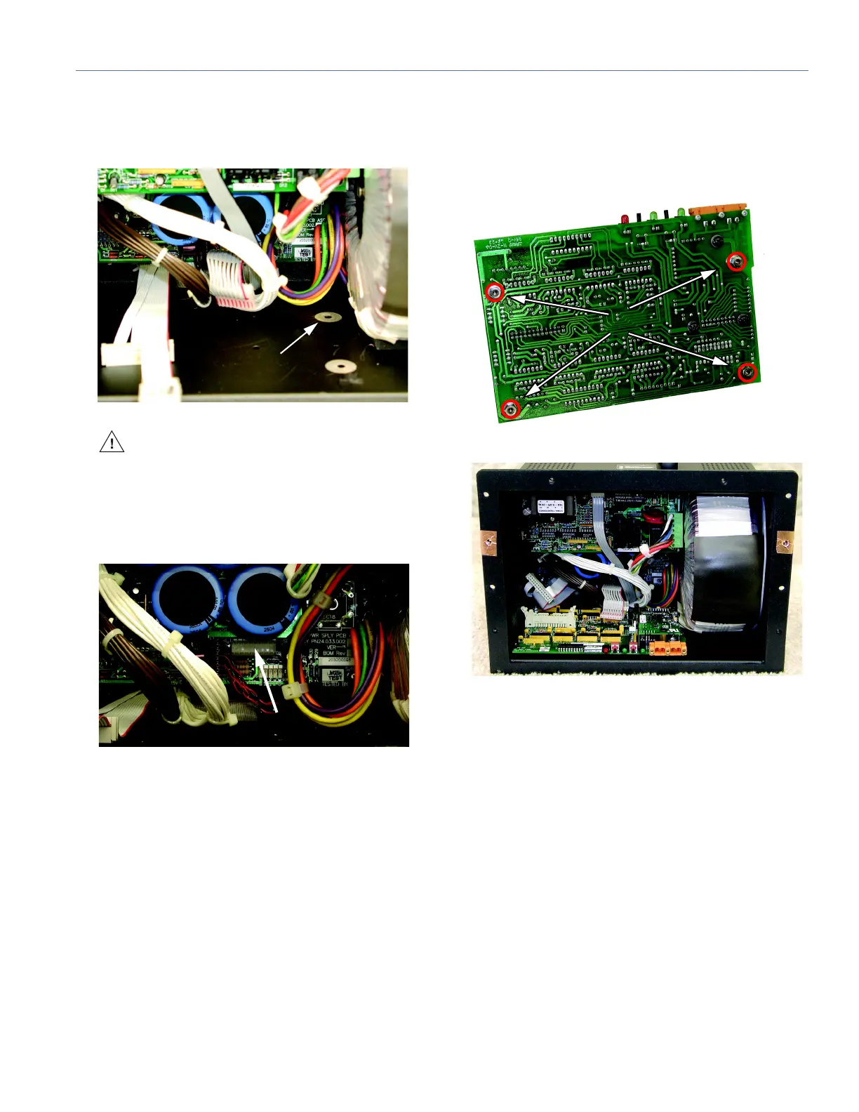
7. Apply one drop of Loctite
®
to each of the four standoffs
on the HP/MP RMS module and then place the module
in the bottom of the power supply chassis with the LEDs
facing out and the standoffs aligned with the four screw
holes in the bottom of the chassis.