CHAPTER 4: HP/MP RMS MODULE
32
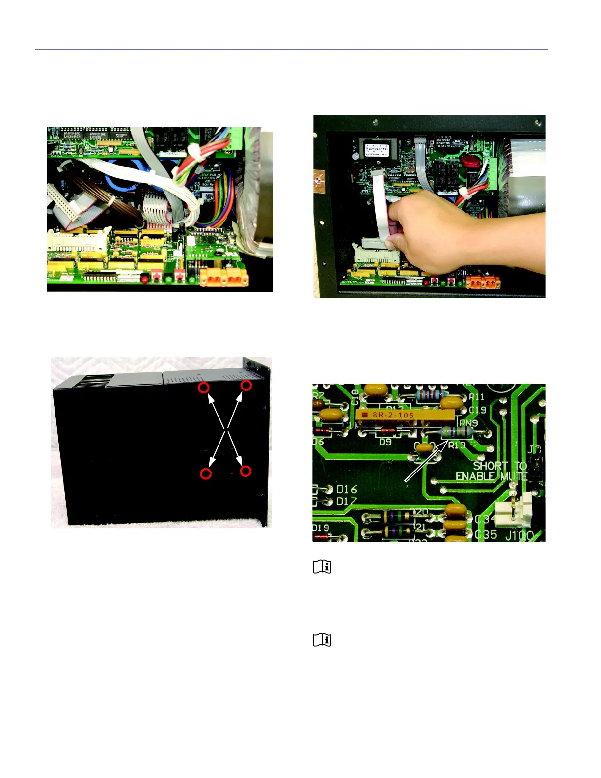
8. Attach the short 9-wire gray ribbon cable from the
HP/MP RMS module to the connector on the power sup-
ply board. Make sure all pins are engaged and that the
connector is firmly seated.
9. While holding the HP/MP RMS module in place, place
the loudspeaker on its side and secure the module using
the four screws included with the kit.
10. Attach the 26-pin connector from the long ribbon cable
to the HP/MP RMS module connector. Make sure to fully
lock the connector.
11. Using an ohmmeter, measure the resistance for R13 on
the HP/MP RMS module. R13 is located about an inch to
the right of the center of the module. The resistance
should measure 10 ohms. If the resistance measures
47 ohms, the module is insufficiently grounded.
NOTE: Insufficient grounding may be caused
by too much paint surrounding the back right
screw hole (see Step 5), or it may be caused by over-
thinning the screw hole (if this is the case, a shorter
screw may fix the problem).
NOTE: The resistance for R13 will not read
10 ohms if the ribbon cable from the HP/MP
RMS module was not connected to the power supply
board (see Step 8).