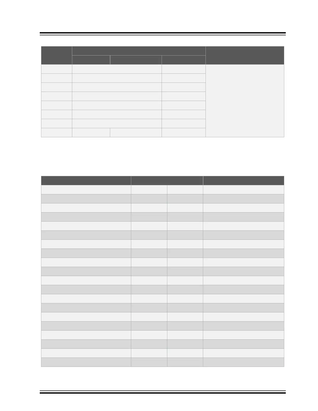
Table 3-7. Host MCU Mode Audio Control Button Header Configurations (J700, J701, and J702)
(1)
Pin Number Jumper Names and Positions Description
J700 J701 J702
1 Mount a jumper on J700 and J701 Open Audio streaming is controlled by on-
board PIC32MX450F256L MCU in
Host MCU mode.
2 Mount a jumper on J700 and J701 Open
3 Mount a jumper on J700 and J701 Open
4 Mount a jumper on J700 and J701 Open
5 Mount a jumper on J700 and J701 Open
6 Mount a jumper on J700 and J701 Open
7 Mount a jumper on J700 and J701 Open
8 Open Open Open
1. To locate these headers on the BM83 EVB, refer to Figure 2-1.
3.1.5.4 BM83 Carrier Board Interface
The following table provides the pin details of J300 and the BM83 module interface with the BM83 EVB.
Table 3-8. Carrier Board Interface (J300) Pin Details
Pin Name Pin Number Pin Name
BK1_O_1V5 1 2 MCLK1
LED3 3 4 DT1
NC 5 6 DR1
RST_N 7 8 SCLK1
DP 9 10 RFS1
DM 11 12 GND
GND 13 14 P3_7
GND 15 16 P3_5
P2_7 17 18 NC
P1_3 19 20 BK2_O_1V8
P1_2 21 22 NC
P0_5 23 24 P0_1
P0_2 25 26 P0_0
P0_3 27 28 P2_3
P0_6 29 30 P0_7
LED2 31 32 UART_TXD
P1_6 33 34 UART_RXD
LED1 35 36 SK2_KEY_AD
P3_4 37 38 PWM
SK1_AMB_DET 39 40 MFB
BM83 EVB
Hardware
© 2019 Microchip Technology Inc.
User Guide
DS50002902A-page 15