9. Appendix C: Digital Microphone Daughter Board
The Digital Microphone Daughter Board has the following components:
• On-board Knowles’ Digital Microphone SPH0641LU4H-1
• Female 5-pin 1x5 header (J1) to interface to BM83 EVB (J503 and J502)
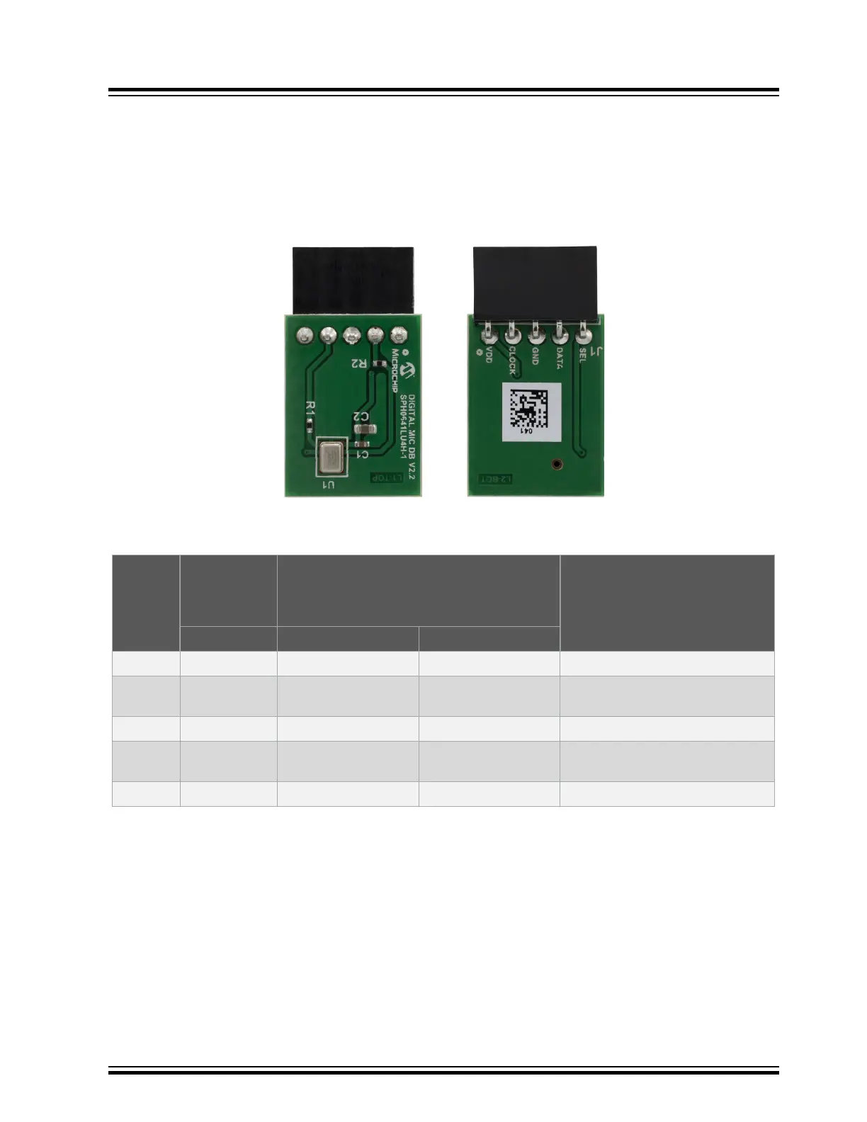
Figure 9-1. Digital Microphone Daughter Board - Top and Bottom View
The following table provides the pin description of the Digital Microphone header.
Table 9-1. Digital Microphone Headers (J1, J503, and J502) Pin Description
Pin
Number
Digital
Microphone
Daughter
Board
BM83 EVB Pin Description
Pin Name (J1) Pin Name (J503) Pin Name (J502)
1 VDD VDD DIGMIC VDD DIGMIC Power supply from BM83 EVB
2 CLOCK DMIC1_CLK DMIC1_CLK Clock input to the microphone from
BM83 module
3 GND GND GND Ground
4 DATA DMIC1_L DMIC1_R PDM output from the microphone to
BM83 module
5 SEL DM1 SELECT DM2 SELECT Select input for microphone
Note:
1. BM83 module supports 1 stereo Digital Microphone (left and right) terminated at J503 and J502 headers
respectively.
2. The VDD power supply for Digital Microphone operation is provided over J509 header on the BM83 EVB.
3. The Select pin should not be left floating and should be connected to high or low. This is achieved by 3-pin
headers J505 and J504 on BM83 EVB.
4. For more details on using Digital Microphone with the BM83, refer to IS208x Config UI Tool User’s Guide.
BM83 EVB
Appendix C: Digital Microphone Daughter Bo...
© 2019 Microchip Technology Inc.
User Guide
DS50002902A-page 57