10. Appendix D: J-Link 6-Pin Adapter Board
J-Link 6-Pin Adapter Board is designed to connect to its targets through a 20-pin cable, provided with the J-Link.
However, BM83 EVB uses a 6-pin connector supporting 2-wire JTAG.
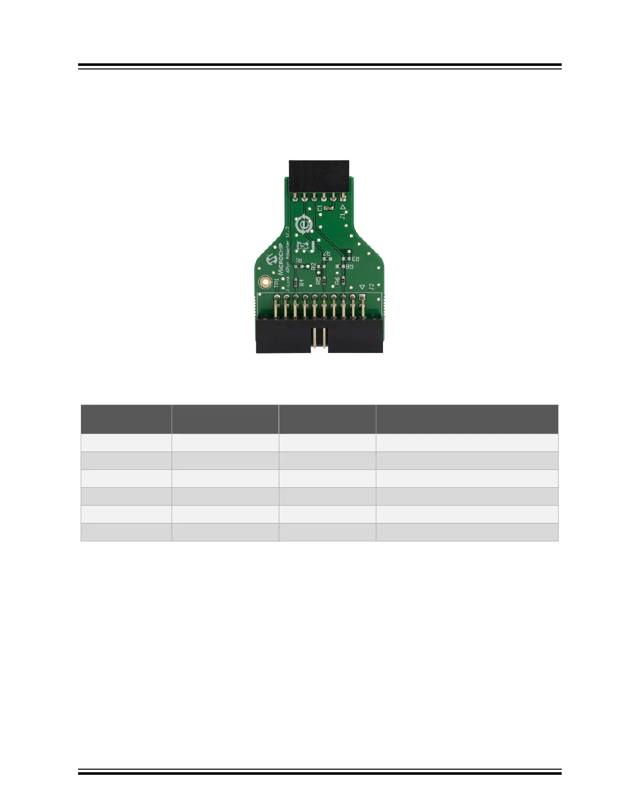
Figure 10-1. J-Link 6-Pin Adapter Board
The following table provides the pin description of J-Link 6-Pin Adapter Board.
Table 10-1. J-Link 6-Pin Adapter Board Pin Description
Pin Number Pin Name on J-Link
Adapter Board
Pin Name on BM83
EVB
Pin Description
1 Reset_n Reset_n Reset
2 3V3 3V3_IO Power supply from BM83 EVB
3 GND GND Ground
4 TDI P1_2 CPU-2 Wire Debug Data
5 TCK P1_3 CPU-2 Wire Debug Clock
6 NC NC NC
BM83 EVB
Appendix D: J-Link 6-Pin Adapter Board
© 2019 Microchip Technology Inc.
User Guide
DS50002902A-page 58