...........continued
Pin Name Pin Number Pin Name
P1_3
11
12 P1_2
UART_RXD
13
14 UART_TXD
P0_7
15
16 P2_6
P2_3
17
18 P1_6
GND
19
20 3V3_IO
3.1.5.7 Digital Microphone Headers
The 5-pin digital microphone header provides an interface to BM83 EVB and the Digital Microphone Daughter Board.
The pin description is provided in the following table.
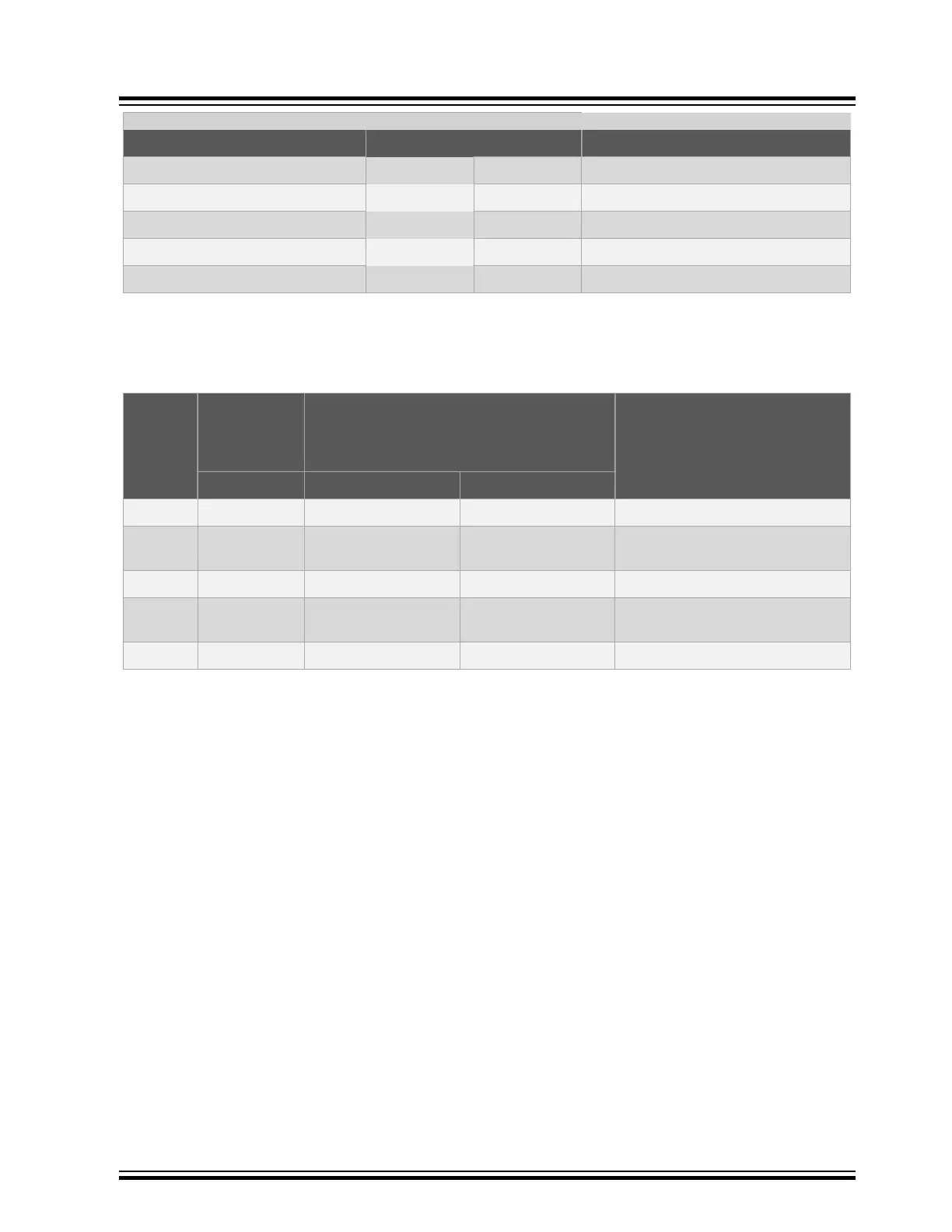
Table 3-11. Digital Microphone Headers (J1, J503, and J502) Pin Description
Pin
Number
Digital
Microphone
Daughter
Board
BM83 EVB Pin Description
Pin Name (J1) Pin Name (J503) Pin Name (J502)
1 VDD VDD DIGMIC VDD DIGMIC Power supply from BM83 EVB
2 CLOCK DMIC1_CLK DMIC1_CLK Clock input to the microphone from
BM83 module
3 GND GND GND Ground
4 DATA DMIC1_L DMIC1_R PDM output from the microphone to
BM83 module
5 SEL DM1 SELECT DM2 SELECT Select input for microphone
BM83 EVB
Hardware
© 2019 Microchip Technology Inc.
User Guide
DS50002902A-page 17