2018 Microchip Technology Inc. DS70005340A-page 77
CAN FD Protocol Module
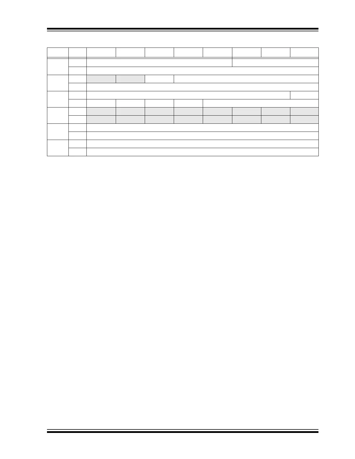
Table 7-1: Transmit Event FIFO Object
Words Bits Bit 15/7 Bit 14/6 Bit 13/5 Bit 12/4 Bit 11/3 Bit 10/2 Bit 9/1 Bit 8/0
TE0
15:8 EID<4:0> SID<10:8>
7:0 SID<7:0>
TE1
15:8
— — SID11 EID<17:13>
7:0 EID<12:5>
TE2
15:8 SEQ<6:0> ESI
7:0 FDF BRS RTR IDE DLC<3:0>
TE3
15:8
— — — — — — — —
7:0 — — — — — — — —
TE4
(1)
15:8 TXMSGTS<15:8>
7:0 TXMSGTS<7:0>
TE5
(1)
15:8 TXMSGTS<31:24>
7:0 TXMSGTS<23:16>
bit 15:11 (TE0) EID<4:0>: Extended Identifier bits
bit 10-0 (TE0) SID<10:0>: Standard Identifier bits
bit 15-14 (TE1) Unimplemented: Read as ‘x’
bit 13 (TE1) SID11: In FD mode, the Standard ID can be extended to 12 bits using r1
bit 12-0 (TE1) EID<17:5>: Extended Identifier bits
bit 15-9 (TE2) SEQ<6:0>: Sequence to keep track of transmitted messages in transmit event FIFO bits
bit 8 (TE2) ESI: Error Status Indicator bit
In CAN to CAN Gateway mode (ESIGM (C1CONH<1>) = 1), the transmitted ESI flag is a “logical OR”
of ESI (TE2) and the error passive state of the CAN controller.
In Normal mode, ESI indicates the error status:
1 = Transmitting node is error passive
0 = Transmitting node is error active
bit 7 (TE2) FDF: FD Frame bit; distinguishes between CAN and CAN FD formats
bit 6 (TE2) BRS: Bit Rate Switch bit; selects if Data Bit Rate is switched
bit 5 (TE2) RTR: Remote Transmission Request bit; not used in CAN FD
bit 4 (TE2) IDE: Identifier Extension bit; distinguishes between base and extended format
bit 3-0 (TE2) DLC<3:0>: Data Length Code bits
bit 15-0 (TE3) Unimplemented: Read as ‘x’
bit 15-0 (TE4) TXMSGTS<15:0>: Transmit Message Timestamp bits
bit 15-0 (TE5) TXMSGTS<31:16>: Transmit Message Timestamp bits
Note 1: TE4 and TE5 (TXMSGTSx) only exit in objects where TEFTSEN (C1TEFCONL<5>) is set.