2018 Microchip Technology Inc. DS70005340A-page 85
CAN FD Protocol Module
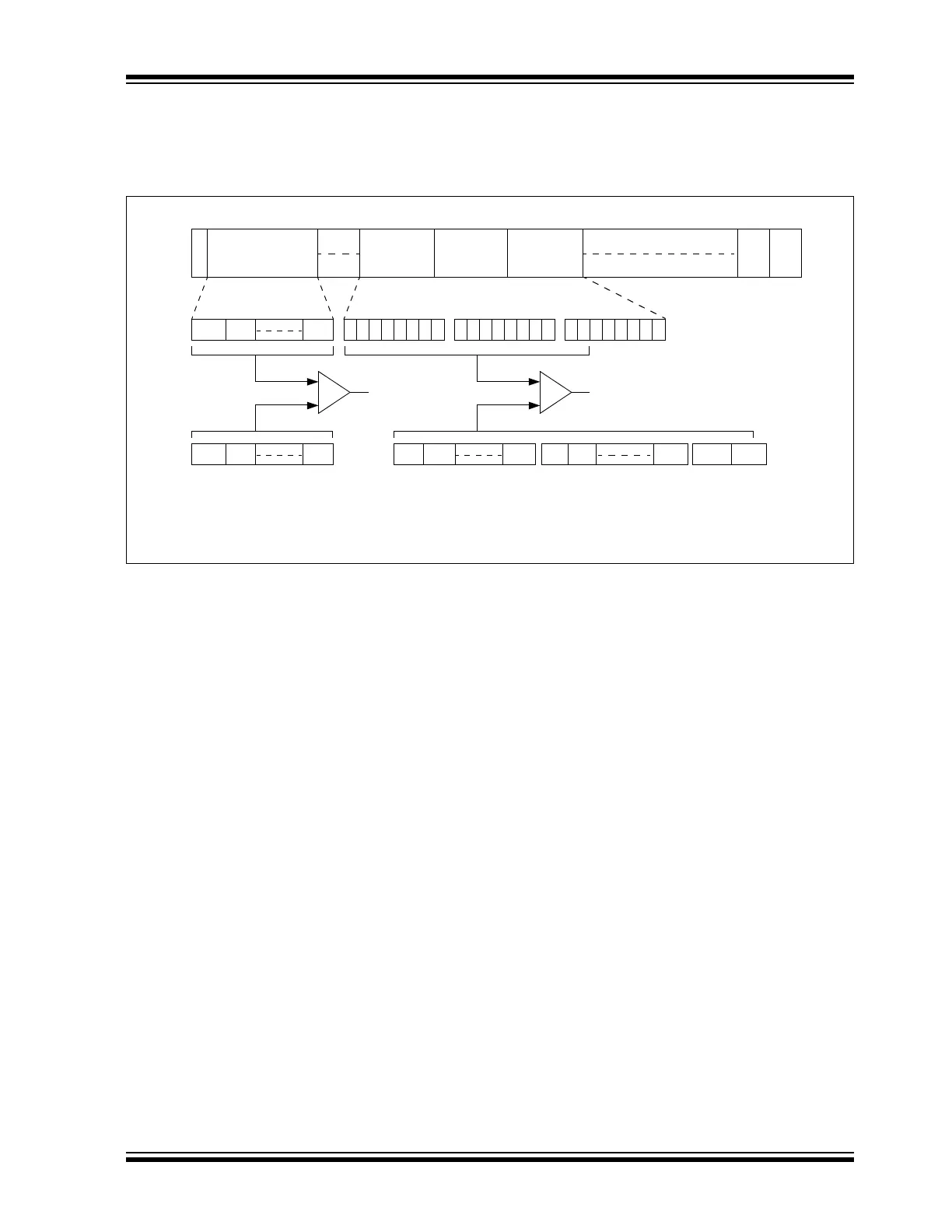
Figure 8-3 illustrates how the first 18 data bits of the received message data payload are
compared with the corresponding EIDx bits of the message acceptance filter (EID<17:0> bits in
the C1FLTOBJxH/L registers). The IDE bit of the received message must be ‘0’.
Figure 8-3: CAN Operation with DeviceNet™ Filtering
SID10 SID9
S
O
F
IDENTIFIER
11 Bits
EOF
7 Bits 3 Bits
SID0
Accept/Reject Message
IFS
DATA BYTE 0
DATA BYTE 1 DATA BYTE 2
76543210 76543210 76543210
Data Byte 0 Data Byte 1 Data Byte 2MESSAGE SID<10:0>
SID10 SID9 SID0
EID0 EID1 EID7
EID8 EID9 EID15 EID1
6
EID17
STANDARD MESSAGE DATA FRAME
MESSAGE ACCEPTANCE FILTER
SID<10:0>
MESSAGE ACCEPTANCE FILTER
EID<0:17>
Note: The DeviceNet™ filtering configuration shown for the EIDx bits is DNCNT<4:0> = 10010.