2018 Microchip Technology Inc. DS70005340A-page 95
CAN FD Protocol Module
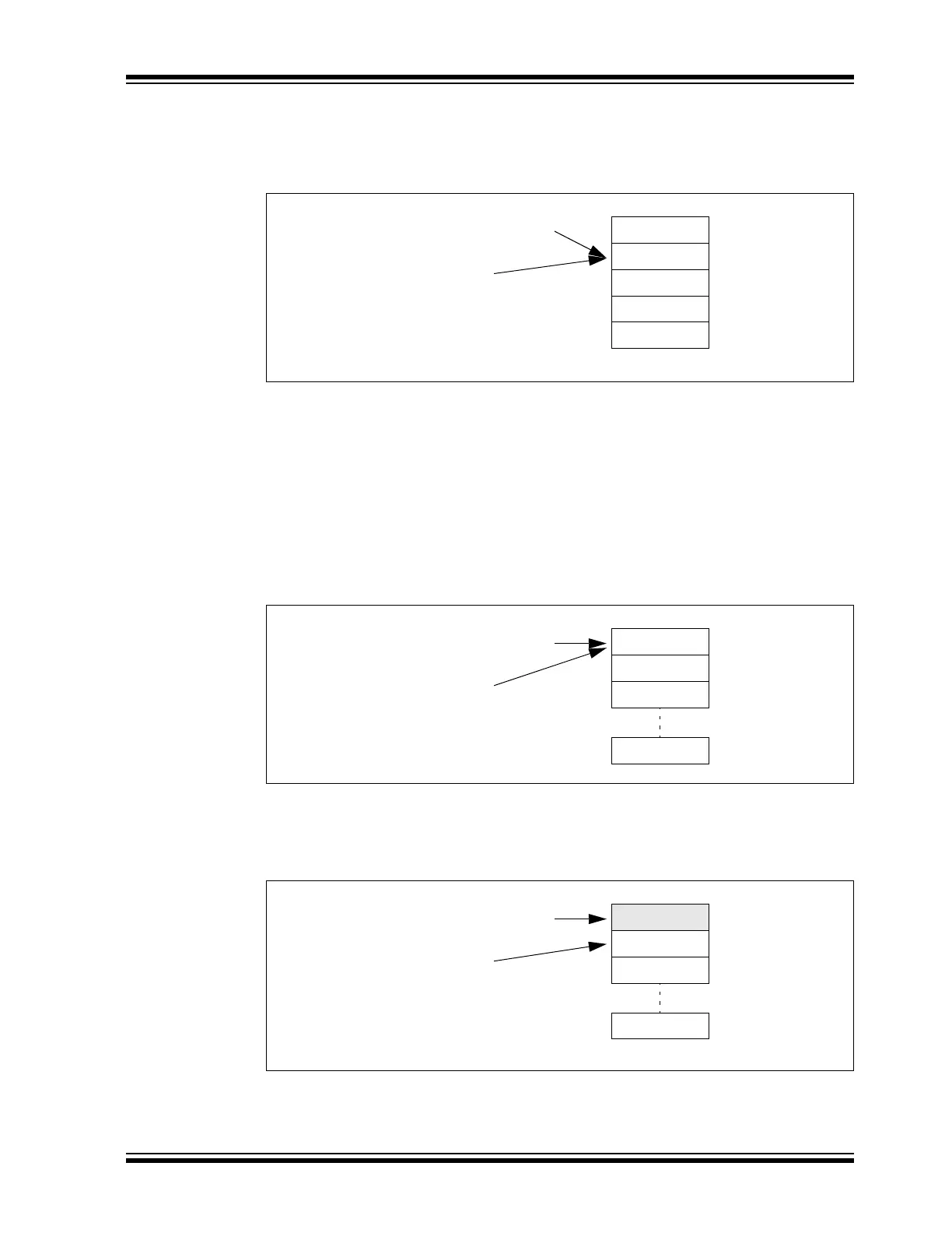
Figure 10-6 illustrates the status of FIFO 1 after MSG1-MSG5 are transmitted. The FIFO is
empty again. All status flags are set and TXREQ is cleared. The user address and the FIFO index
point to MO1 again.
Figure 10-6: FIFO 1 – FIFO Fully Transmitted
10.3 Receive FIFO Behavior
FIFO 2 is configured as an RX FIFO. C1FIFOCON2L and C1FIFOCON2H are used to control
the FIFO. C1FIFOSTA2 contains the status flags and the FIFO index (FIFOCIX). C1FIFOUA2L
and C1FIFOUA2H contain the user address of the next message object to read.
Figure 10-7 through Figure 10-14 illustrate how the status flags, user address and FIFO index
are updated.
Figure 10-7 shows the status of FIFO 2 after the Reset. Message objects, MO0 to MO15, are
empty. All status flags are cleared. The user address and the FIFO index point to MO0.
Figure 10-7: FIFO 2 – Initial State
Figure 10-8 illustrates the status of FIFO 2 after the first message (MSG0) is received. MO0 now
contains MSG0. The FIFO index now points to MO1. RFNIF is set since the FIFO is not empty
anymore.
Figure 10-8: FIFO 2 – First Message Received
Figure 10-9 illustrates the status of FIFO 2 after MSG0 is read. The user application reads the
message from RAM and sets the UINC bit (C1FIFOCON2L<8>). The user address increments
and points to MO1. The FIFO index is unchanged. The FIFO is empty again. All flags are cleared.
MO0
MO1
MO2
MO3
MO4
C1FIFOUA1L = 0x218
C1FIFOSTA1:
FIFOCIx = 1
TFEIF = 1
TFHIF = 1
TFNIF = 1
C1FIFOCON1L:
TXREQ = 0
MO0
MO1
MO2
MO15
C1FIFOUA2L = 0x338
C1FIFOSTA2:
FIFOCIx = 0
RFFIF = 0
RFHIF = 0
RFNIF = 0
RXOVIF = 0
MO0/MSG0
MO1
MO2
MO15
C1FIFOUA2L = 0x338
C1FIFOSTA2:
FIFOCIx = 1
RFFIF = 0
RFHIF = 0
RFNIF = 1
RXOVIF = 0