dsPIC33CK Low-Voltage Motor Control Board User’s Guide
DS50002927A-page 20 2020 Microchip Technology Inc.
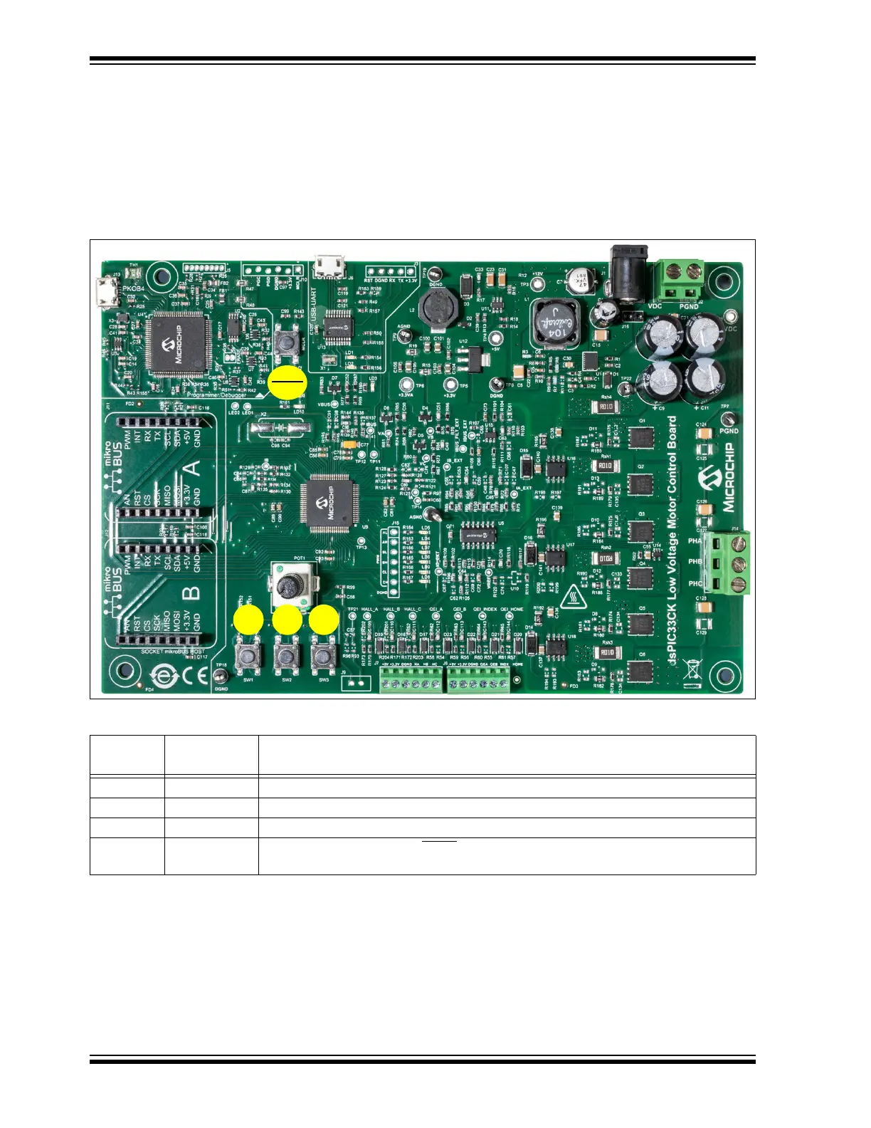
2.3.2 Push Buttons
The push buttons provided on the Motor Control Board are shown in Figure 2-4 and
summarized in Tab le 2- 12.
The push buttons, SW1, SW2 and SW3, are provided to control motor operations; for
example, starting or stopping the motor. The functions of these push buttons are
defined by the motor control application firmware.
FIGURE 2-4: PUSH BUTTONS – dsPIC33CK LOW-VOLTAGE MOTOR CONTROL BOARD
TABLE 2-12: PUSH BUTTONS
SI #
Push Button
Designator
LED Indication
1 SW1 Push button provided for general purpose (BUTTON1).
2 SW2 Push button provided for general purpose (BUTTON2).
3 SW3 Push button provided for general purpose (BUTTON3).
4 SW4 This push button is tied to the MCLR
pin of the dsPIC33CK256MP508. Pressing this button
will reset the dsPIC
®
DSC.