Lessons
2012 Microchip Technology Inc. DS41628B-page 53
DS1 is connected to RC0 and DS2 to RC1 and so forth. A shift to the right would actu-
ally be turning on the LEDs from right to left. This can be better explained in the follow-
ing figures.
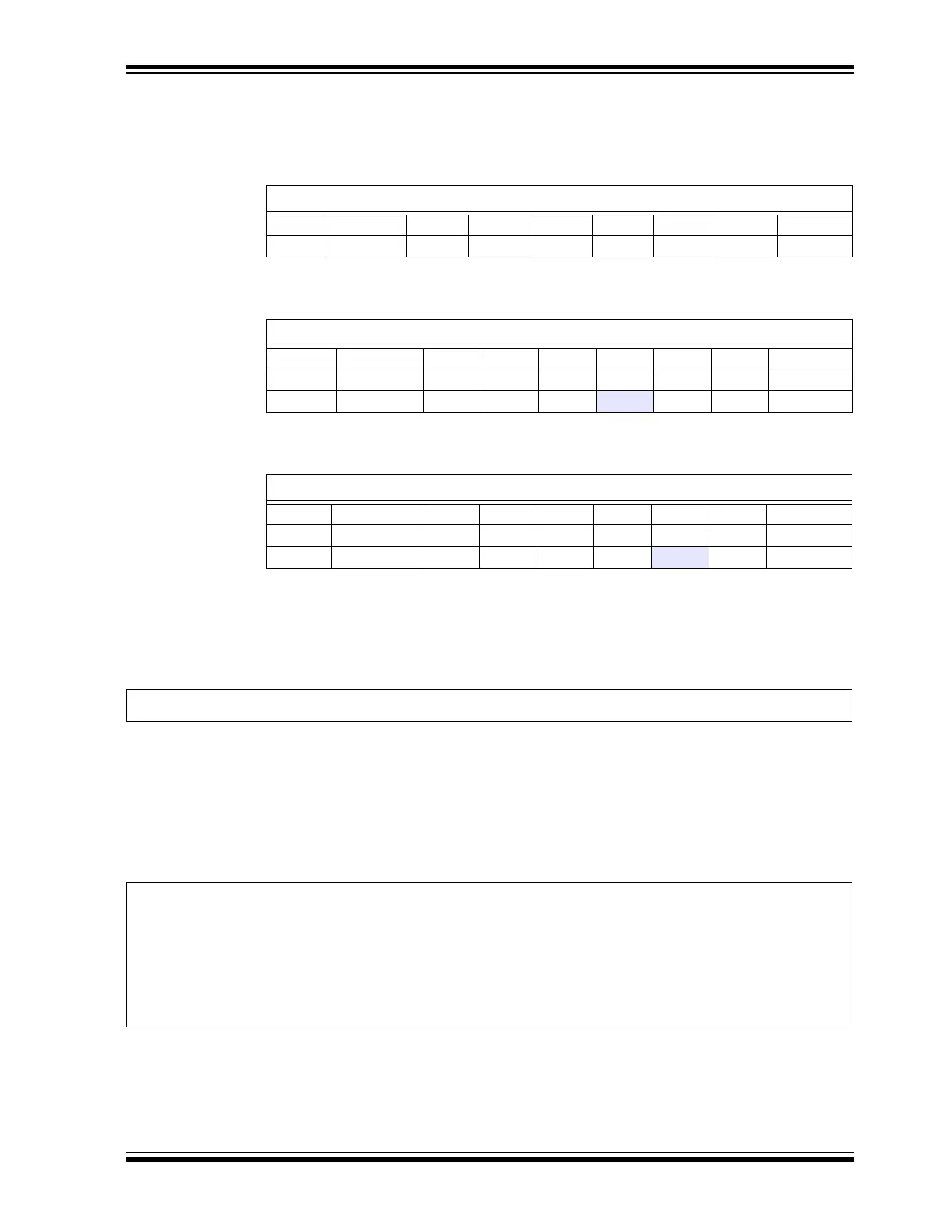
Start of program begins with lighting up DS4;
After the delay, a logic shift to the right is performed:
Now DS3 is lit. The carry bit now contains whatever was previously in
LATCbits.LATC0. In this case, it was ‘0’. The program then checks if the carry bit was
set. This will only be true if DS1 was previously lit, and then an lsrf was performed.
Now, the carry bit would be set and the following line would be executed.
EXAMPLE 3-15:
Now the program will restart the sequence by relighting DS4. It is important to note that
the MSb, bit 7, will ALWAYS be cleared. This is due to the nature of the lsrf instruc-
tion.
3.4.6.2 PIC18
The PIC18 does not have the same logical shift instruction as the enhanced mid-range.
EXAMPLE 3-16:
TABLE 3-11: PIN TO LED MAPPING
LATC
Bit #MSb (7)654321LSb (0)
LED — — — — DS4 DS3 DS2 DS1
TABLE 3-12: LED ROTATE
LATC
Bit # MSb (7)654321LSb (0)
LED — — — — DS4 DS3 DS2 DS1
value 0 000
100 0
TABLE 3-13: LED ROTATE
LATC
Bit # MSb (7)654321LSb (0)
LED — — — — DS4 DS3 DS2 DS1
value 0 000010 0
bsf LATC, 3 ;yes, it did and now start the sequence over again by turning on DS4
Rotate:
rrcf LATC,f ;rotate the LEDs (through carry) and turn on the next LED to the right
btfss STATUS,C ;did the bit rotate into the carry (i.e. was DS1 just lit?)
goto MainLoop ;nope, repeat this program forever
bsf LATC, 3 ;yes, it did and now start the sequence over again by turning on DS4
bcf STATUS, C ;clear the carry
goto MainLoop ;repeat this program forever