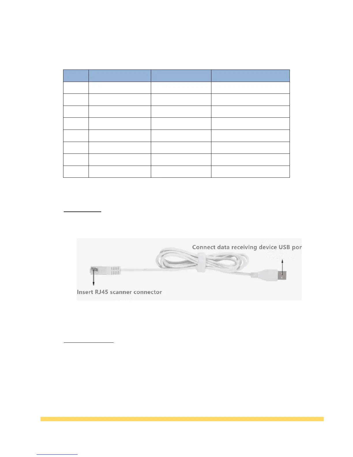
The usage steps are as follows:
1, first connect the RJ45 plug on the data line with the scanner;
2. Connect the RS232 interface on the data cable to the PC (or control board).
3. Then connect the USB port of the data cable to the 5V power supply, which can be the USB
port on the computer, or other USB ports that can provide 5V power supply;
4. After the power is turned on, the auxiliary lighting of the product will be turned on. After
hearing the “buzz” sound, the scanner will enter the working state.