20 DIGITAL RACK MIXER M32R User Manual
1.11 Talkback
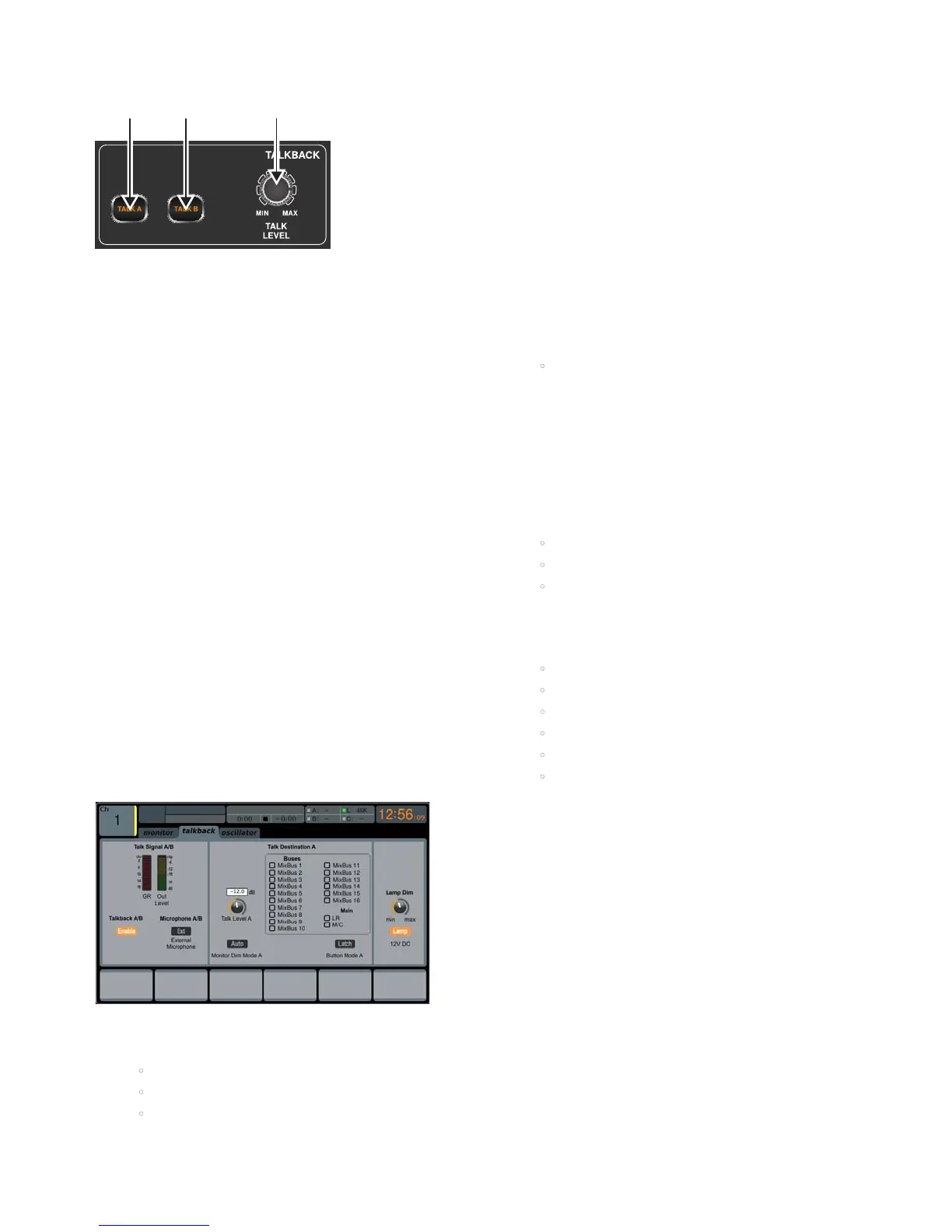
(1) & (2) - TALK A / B
Select the destination of the Talkback mic signal with either the TALK A or
TALK B buttons. Press the VIEW button in the MONITOR section to edit the
Talkback routing for A and B.
(3) TALK LEVEL Rotary Control
Adjust the level of the Talkback volume with the TALK LEVEL rotary control.
1.11.1 Operation
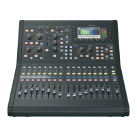
talkback Tab
The TALKBACK screen oers various adjustments for the talkback paths of the
console, such as destination of the talkback signal and more.
To adjust the various settings on the talkback tab, perform the
following steps:
1. The screen displays a multi-segment level meter showing the strength
of the talkback signal as it has currently been set. It also displays a
multi-segment gain reduction meter, showing the user how much
compression has been automatically applied to the talkback signal.
2. Tap the rst push encoder to enable the talkback circuit. The internal/
external talkback microphone will now transmit audio to the talkback
path’s assigned destination.
3. Adjust the third encoder to set the gain of the talkback signal. This is
an additional gain stage that follows the initial gain stage set by the top
panel TALK LEVEL control.
4. Tap the third encoder to toggle on/o the talkback circuits ‘auto-dim’
function. This function is useful in a studio setting, and will
automatically dim the control room outputs when the talkback circuit
is active. This prevents the talkback microphone from picking up too
much sound from the nearby studio monitors.
5. Adjust the fourth encoder to scroll through the various talkback
destinations, which include:
• Mix Bus 1-16
• LR Bus
• Centre/Mono Bus.
6. Tap the fourth encoder to activate any talkback destination when it
is currently selected. Multiple talkback destinations can be selected,
allowing the talkback signal to reach many destinations at the
same time.
7. Tap the fth encoder to toggle the dedicated top-panel talkback
buttons between latching and non-latching operation.
oscillator Tab
The oscillator tab oers controls for the console’s onboard oscillator, a very
handy tool that can be used for setting up PA systems and testing various
signal ow paths without the need for a live source feeding a microphone.
Settings include oscillator type, frequency, volume and routing destinations.
To adjust the various settings on the oscillator tab, perform the
following steps:
1. Adjust the rst push encoder to set the level of the onboard oscillator.
2. Tap the rst encoder to toggle the oscillator on or o.
• The Main Display shows a multi-segment level meter that shows
the current level of the oscillator.
3. Adjust the second encoder to set the frequency of the primary
onboard oscillator.
4. Adjust the third encoder to set the frequency of the alternate onboard
oscillator.
5. Tap the third encoder to alternate between Sine F1 and Sine F2.
6. Adjust the fourth encoder to select the type of oscillator to be used.
Choices include:
• Sine Wave
• Pink Noise
• White Noise.
7. Tap the fourth encoder to engage the selected oscillator type.
8. Adjust the sixth encoder to select a destination for the
onboard oscillator. Choices include:
• Mix Bus 1-16
• Main L Bus
• Main R Bus
• Main L+R Bus
• Main Centre / Mono
• Matrix Outputs 1-6.
9. Tap the sixth encoder to assign the selected oscillator destination.
(1) (1) (3)