23 DIGITAL RACK MIXER M32R User Manual
2. Main Display
2.1 Main Display - Top Section
The top section of the Main Display permanently covers useful
status information. The top left corner shows the selected channel number,
its user-assigned name and the selected icon. The next block shows the
current scene number and name in amber, as well as the next upcoming scene.
The centre section displays the playback le name along with elapsed and
remaining time, and a recorder status icon. The next block to the right has
four segments to show the status of the AES50 ports A and B, the Card slot,
and the audio clock synchronisation source and sample rate. Small green square
indicators show proper connectivity. The rightmost block shows the console time,
which can be set under Setup - Cong.
2.1.1 Home
The HOME screen contains a high-level overview of the selected input or output
channel, and oers various adjustments not available through the dedicated
top-panel encoders.
The HOME screen is divided into the following tabs:
home: General signal path for the selected input or output channel.
cong: Allows selection of signal source/destination for the channel,
conguration of insert point, and other settings.
gate: Controls and displays the channel gate eect beyond those oered by
the dedicated top-panel encoders.
dyn: Controls and displays the channel dynamics eect (compressor) beyond
those oered by the dedicated top-panel encoders.
eq: Controls and displays the channel EQ eect beyond those oered by the
dedicated top-panel encoders.
sends: Controls and displays the channels sends, such as sends metering and
sends muting.
main: Controls and displays the selected channel’s output.
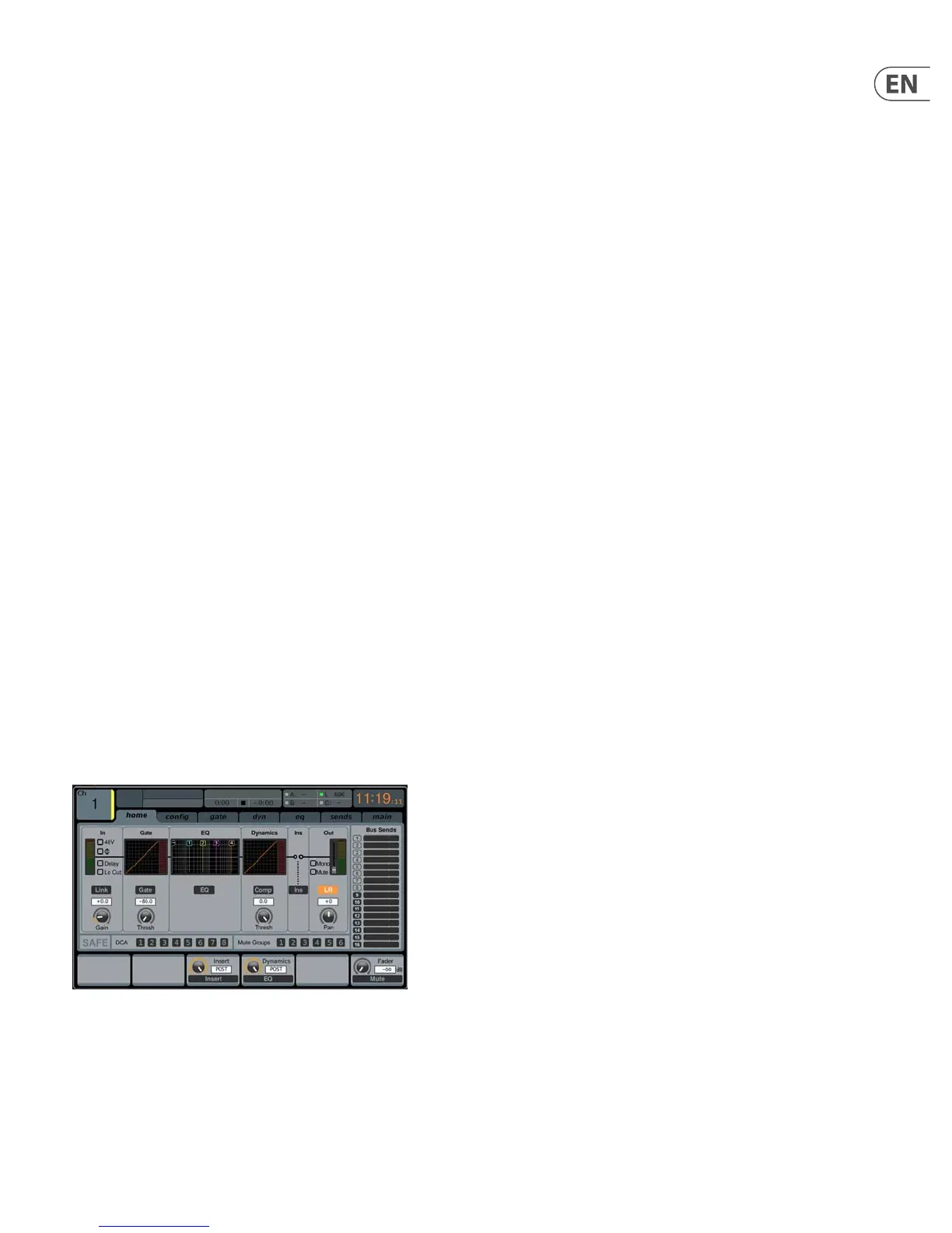
home
The home tab of the HOME screen displays a general signal path for the currently
selected input or output channel. It visually displays various parameters of the
input, gate, insert point, EQ, dynamics, output path and buses.
The home tab contains the following parameters (divided into two pages)
that can be adjusted using the six push encoders.
Page 1
1. Turn the rst push encoder to adjust the input gain (trim) of
the channel.
2. Tap the rst encoder to link the channel with its adjacent channel.
3. Adjust the second encoder to set the threshold of the channel
noise gate.
4. Tap the second encoder to toggle the channel noise gate in/out of the
signal path.
5. Adjust the third encoder to toggle the channel’s insert point between
pre-fader and post-fader status.
6. Tap the third encoder to toggle the channel insert in/out of the
signal path.
7. Adjust the fourth encoder to toggle the channel dynamics between
pre-EQ and post-EQ status.
8. Tap the fourth encoder to toggle the channel EQ in/out of the
signal path.
9. Adjust the fth encoder to set the threshold of the channel compressor.
10. Tap the fth encoder to toggle the channel compressor in/out of the
signal path.
11. Adjust the sixth encoder to pan the selected channel within the main
stereo output.
12. Tap the sixth encoder to assign the selected channel to the main
stereo output.
Page 2
1. Adjust the rst push encoder to select the console channel currently
controlled by the HOME screen.
2. Tap the rst encoder to toggle +48V phantom power on/o for the
currently selected input.
3. Tap the second encoder to toggle the phase ip on/o for the currently
selected channel.
4. Adjust the third encoder to select to which of the eight DCA groups the
currently selected channel will be assigned.
5. Tap the third encoder to assign the currently selected channel to the
selected DCA group.
6. Adjust the fourth encoder to select to which of the six mute groups the
currently selected channel will be assigned.
7. Tap the fourth encoder to assign the currently selected channel to the
selected mute group.
8. Tap the fth encoder to toggle solo on/o for the currently
selected channel.
9. Turn the sixth encoder to adjust the fader level for the currently
selected channel.
10. Tap the sixth encoder to toggle mute on/o for the currently
selected channel.