line L
PUSH
insert
mic
line
in
direct
out
(stereo only)
line in left
line in right
51
Mono Input ChannelsMono Input Channels
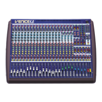
The Verona channel inputs are located on the rear of the console.
Each mono channel provides
one line in quarter-inch TRS balanced jack socket
The insert point is unbalanced and requires a conventionally wired insert lead where:
one insert point on a single TRS jack socket.
one direct output on a single impedance balanced quarter-inch jack socket
one mic XLR female
- Channel Signal Send
- Channel Signal Return
- Signal Common Ground
The direct out and insert points operate at a nominal level of 0dBu.
Balanced XLR and Jack inputs are conventionally wired:
- 1. Screen - 2. Hot Signal - 3. Cold Signal
- T. Hot Signal - R. Cold Signal - S. Screen
: Direct outputs as standard are set post EQ pre mute, however there is an
internal jumper which will set them pre EQ and pre insert
Tip
Ring
Sleeve
XLR
TRS
Note
(refer to the service manual
or contact your authorised Midas service agent).
ins
mic gain
+30 +45
+60+15
mic
padpower
48v -15
O
20
60
160
400
hi-pass
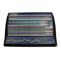
Front Panel
The actual number of mono input channels on your Verona will depend upon your choice of frame, however functionality
remains the same
Rear Panel
48V Power - When depressed, the Verona
will apply 48 volts phantom power to the
microphone input. This is used to power
condenser microphones, direct inject boxes
and other devices that require phantom
power.
The red phantom LED will light to indicate
that 48V phantom is in operation.
-15dB Pad - The Pad switch provides 15dB
attenuation to the input signal allowing for
the connection of high output microphones
and line level signals without overloading
the channel input amplifier. Overloads are
indicated on the in-channel meter by the
red LED at the top.
Mic Gain - The mic gain is continuously
variable from +15dB to +60dB (0dB to
+45dB with the Pad enabled). The actual
value of the gain required will depend upon
the source and should ideally be set such
that peaks in level on the input should not
cause the input amplifier to overload
(occasional peaks of +12dB is okay, +18dB
is too high).
Mic Ø - The mic phase switch, when
depressed, causes a 180 degree phase
change (with respect to the input signal) to
occur in the input amplifier such that the
channel signal will have opposite polarity to
the input signal.
The mic phase switch is commonly needed
where two microphones are used facing
each other (for example when using a
microphone on both the top and bottom of a
snare drum). Ordinarily the two
microphones would be out of phase causing
cancellation when the console sums the two
signals into the output. Reversing the phase
of one signal causes the microphones to
have the same phase and no cancellation.
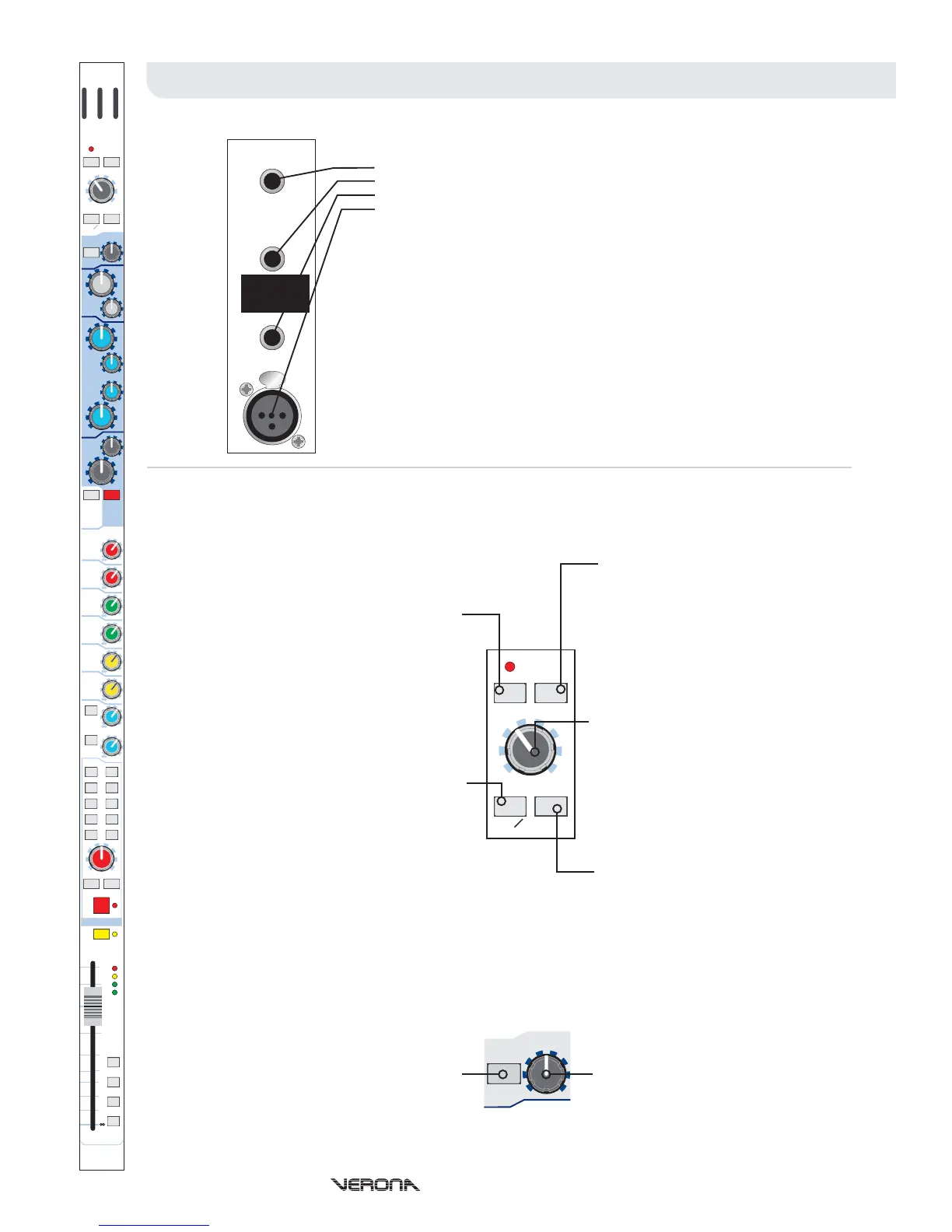
Ins - The ins switch enables the channel
insert point by connecting the insert return
to the channel signal path so that
compressors, gates or other dynamic and
signal processors or effects can be used.
Hi-Pass - The high pass switch enables
high pass filter on the microphone input.
This is commonly used to remove handling
noise, bass rumble through coupling with
the stage or mains hum.
High Pass Frequency - The cutoff
frequency of the high pass filter is
continuously variable from 20Hz to 400Hz.
Operators Manual - Page 8
ins
MIDAS
mic gain
100
300 1k
2k
20
50 100
200
400
3k
8k
1k
2k
5k 10k
20k
20
60
160
400
-15 +15
-15 +15
-15 +15
-15
+15
+30 +45
+60+15
mic
padpower
48v -15
eq
on
0
0
0
0
0
0
0
0
+6
+6
+6
+6
+6
+6
+6
+6
eq
aux pre
off
treble
hi-mid
lo-mid
bass
hi-pass
pan
c
lr
groups master
pan s i s
-18
0
12
18
mute 1
mute 2
mute 3
mute 4
aux 1
aux 2
aux 3
aux 4
aux 8
mono
groups
stereo
1-2
5-6
7-8
3-4
pre
pre
aux 7
aux 6
aux 5
O
10
10
5
5
0
20
15
30
40
SOLO
MUTE
 Loading...