64 Chapter 9: Setting Up The System
XL8 Control Centre
Quick Reference Guide
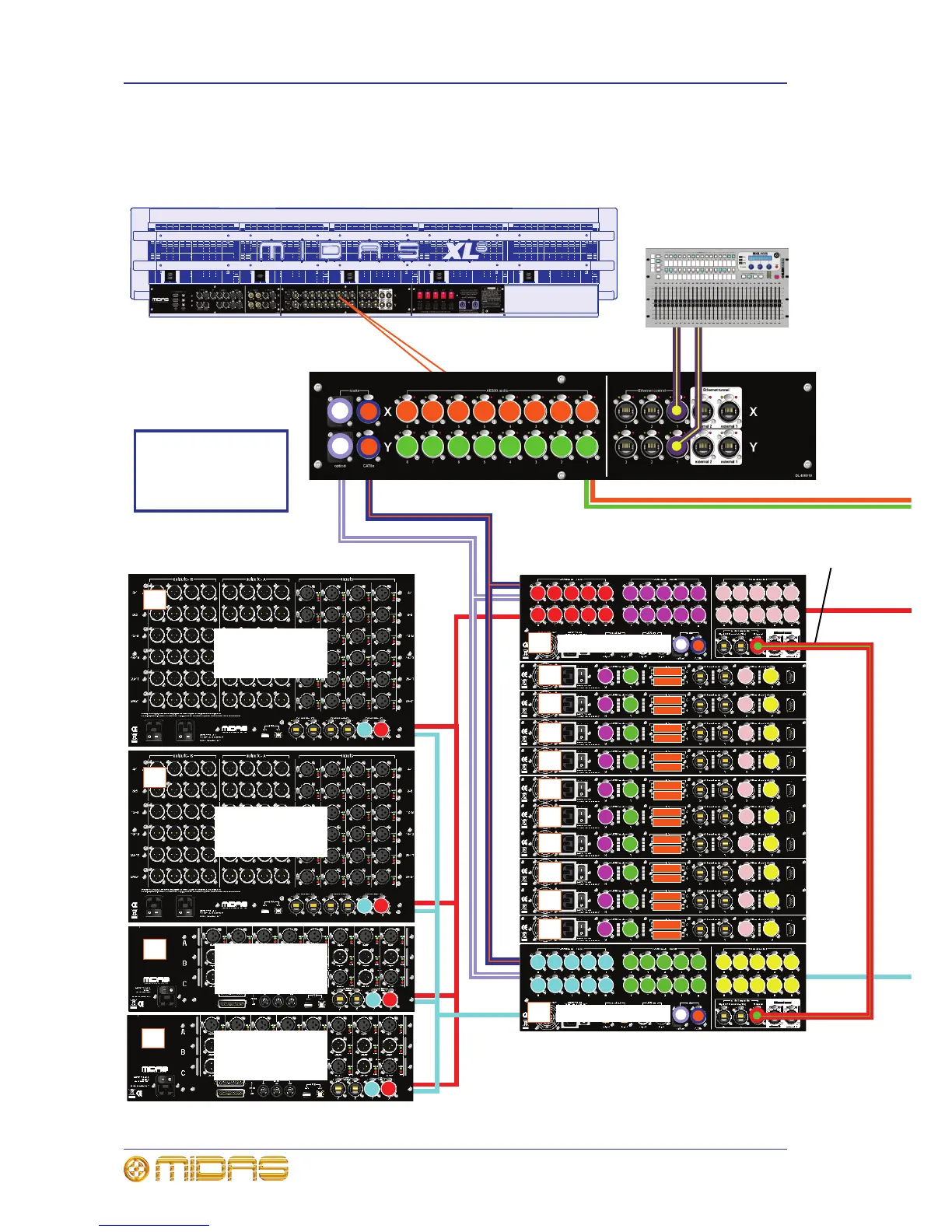
XL8 system interconnections
This diagram shows the network interconnections for a typical FOH XL8 system.
1
1
1
2
5
1
2
5
12345678
12345678
A
A
B
Rear of FOH XL8 Control Centre
Stage rack 1
Note: All connections
are dual redundant, so
the system can operate
quite normally using
either the X or Y cables.
5 4 3 2 1
6 7 8 9
10
5 4 3 2 1
6 7 8 9
10
5 4 3 2 1
6 7 8 9
10
2
2
3
3
4
4
5
5
6
6
7
7
8
8
9
9
1010
2
2
3
3
4
4
5
5
6
6
7
7
8
8
9
9
1010
C
C
C
C
C
C
C
C
C
D
Y
Router/router
inter-connection
RAPIDE
Connect to both X and
Y networks
6
6
B
ID: 1
Inputs: 1 - 24
IP: 192.168.32.1
ID: 2
Inputs: 25 - 48
IP: 192.168.32.2
ID: 3
Config: O/O/D
IP: 192.168.36.3
ID: 4
Config: O/O/D
IP: 192.168.36.4
AMU 2
AMU 3
AMU 4
AMU 5
AMU 6
AMU 7
AMU 8
AMU 9
AMU 10
IP: 192.168.128.10
ID and IP numbers of the above DSPs run sequentially
between AMU 1 and AMU 10:
ID: AMU 1 = 11 through to AMU 10 = 20, inclusive.
IP: AMU 1 = 192.168.20.11 through to AMU 10 =
192.168.20.20, inclusive.
5 4 3 2 1
6 7 8 9
10
5 4 3 2 1
6 7 8 9
10
5 4 3 2 1
6 7 8 9
10
D
Stage rack 2
X
IP: 192.168.128.9
2
2
1
1
C
AMU 1
2
2
2
2
1
1
 Loading...