MCAC-RTSM-2009-09 Midea Heat Pump Water Heater Technical Manual
34
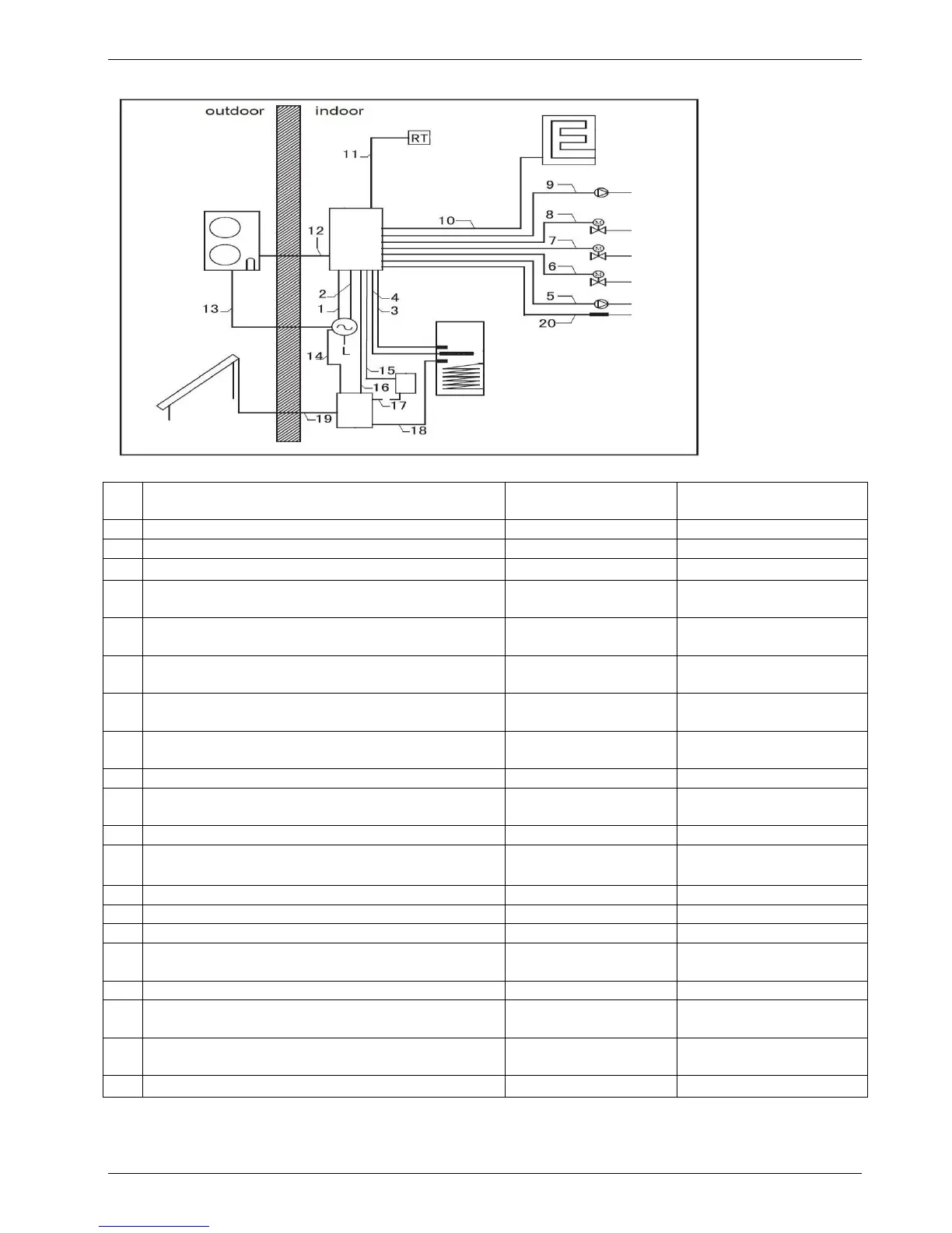
12.2 Electrical connection diagram and cable specification
cable specification
Power supply cable for indoor unit
Power supply cable for electric heater
Power supply cable from indoor unit to Sanitary
hot water tank
Power supply cable for Pump of solar kit (Pump
3)
Power supply cable for motorized 2-way valve,
SV3
Power supply cable for motorized 2-way -valve,
SV2
Power supply cable for motorized 2-way valve,
SV1
Power supply cable for auxiliary pump (Pump2)
Communication cable between indoor unit and
boiler
Communication cable between indoor unit and
outdoor unit
3×0.5 mm
2
(3 -Shield wire)
Power supply cable for outdoor unit
Power supply cable for solar pump station
Power supply cable for the pump of solar kit
Signal input from solar pump station to indoor
unit
Power supply cable for the pump of solar kit
Sanitary hot water tank temperature sensor
cable
Sanitary hot water tank temperature sensor
cable
Water circuit temperature senor T1B cable