20
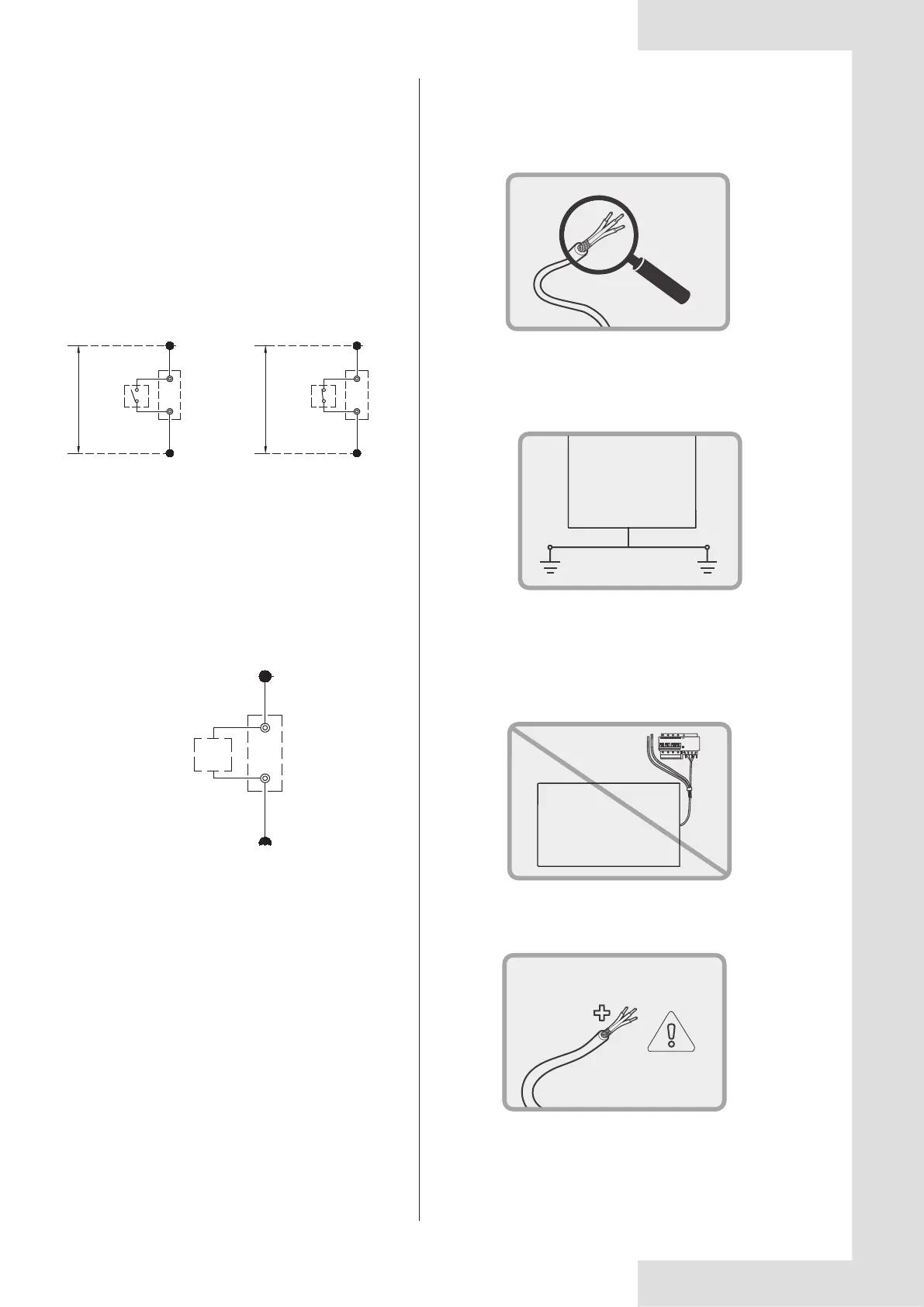
8.4.13 Control system and installation precautions
8.4.12 Wiring of “ALARM” port
electric control box
“ALARM” port
Device provided
by user
Connect the device provided by user to the “ALARM” ports of the
module units as follows.
If the unit is operating unnormally,the ALARM port is closed,
otherwise,the ALARM port is open.
The ALARM ports are on the main control board. See the wiring
diagram for details.
a. Use only shielded wires as control wires. Any other type of wires
may produce a signal interference that will cause the units to
malfunction.
b. The shielding nets at both ends of the shielded wire must be
grounded. Alternatively, the shielding nets of all shielded wires
are interconnected and then connected to earth through or one
`metal plate.
c. Do not bind the control wire, refrigerant piping and power cord
together. When the power cord and control wire are laid parallel,
they should be kept at a distance of more than 300 mm to prevent
signal source interference.
d. Pay attention to the polarity of the control wire when conducting wiring
operations.
Fig. 8-15 Wiring of “ALARM” port
Uint
Uint
Fig. 8-16-1 Control system and installation precaution (a)
Fig. 8-16-2 Control system and installation precaution (b)
Fig. 8-16-3 Control system and installation precaution (c)
Fig. 8-16-4 Control system and installation precaution (d)
0# electric
control box
“TEMP-SWITCH” port
Power (DC 12V)
Main control board is provided
0# electric
control box
“TEMP-SWITCH” port
First target water temperature
Power (DC 12V)
Main control board is provided
Second target water temperature
Fig. 8-14 Wiring of “TEMP-SWITCH” weak electric port
The function of “TEMP-SWITCH” must be set by wired controller
for two setting water temperature. For cooling and heating mode.
Wiring method:
For 65KW and 110KW: Shorting the terminal block CN110 at
slave board inside the electric control box to chose the target
water temperature
8.4.11 Wiring of “TEMP-SWITCH” weak
electric port
 Loading...