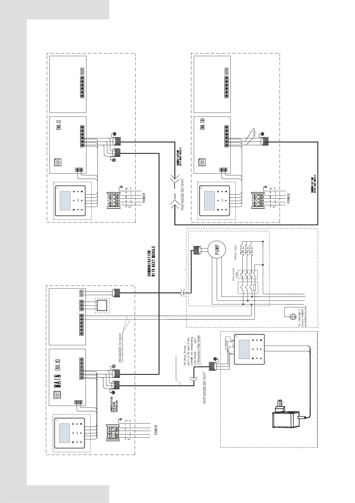
Fig. 8-17 Networking communication schematic of main unit and auxiliary unit for 65KW
8.4.14 Wiring instances
If multiple units are connected in cascade, the unit address should be set on the DIP switch ENC1. With 0-F being valid, 0 indicates
the master unit and 1-F indicate slave units.
L1 L2 L3 N
Th e le ng th o f wi re
sh ou ld b e sh or ter
th an 5 00 m
10 0Ω
Notes
The wiring diagram of auxiliary heaters
is just for reference ,please follow the
instructions of corresponding auxiliary
heater products.
Please choose such accessory as power
wire , switch of auxiliary heater according to
the actual parameter of products and national
Contactor
Power Transformer
OUTPUT:8.5 V
~
for pipeline
MAIN CONTROL
WIRECONTROLER
X Y
X
Y
X
Y
XT3
L1 L 2 L3
POWER 380-415V 3N~50Hz
ENC1
AC1
AC2
MAIN CONTROL
WIRECONTROLER
X
Y
E
RD
YE
BK
BR
WH
POWER 380-415V 3N~50Hz
RVV-300/500 5X16mm
2
X
Y
E
AC1
AC2
RD
YE
BK
BR
WH
Main board
Slave board
CN22
CN46
CN119
HEAT1
12 0Ω
POWER 380-415V 3N~50Hz
RVV-300/500 5X16mm
2
CN108
GND
0-10V
GND
IN2
CN125
COM
NC
NO
21
MAIN CONTROL
WIRECONTROLER
XT3
L1 L 2 L3
ENC1
X
Y
E
RD
YE
BK
BR
WH
X
Y
E
AC1
AC2
RD
YE
BK
BR
WH
Main board
Slave board
CN22
CN46
CN119
HEAT1
MAIN CONTROL
WIRECONTROLER
XT3
L1 L 2 L3
ENC1
X
Y
E
RD
YE
BK
BR
WH
X
Y
E
AC1
AC2
RD
YE
BK
BR
WH
Main board
Slave board
CN22
CN46
CN119
HEAT1
POWER 380-415V 3N~50Hz
RVV-300/500 5X16mm
2
SLAVE
SLAVE
CN108
CN108
3-way
valve
 Loading...