If multiple units are connected in cascade, the unit address should be set on the DIP switch ENC1. With 0-F being valid, 0 indicates
the master unit and 1-F indicate slave units.
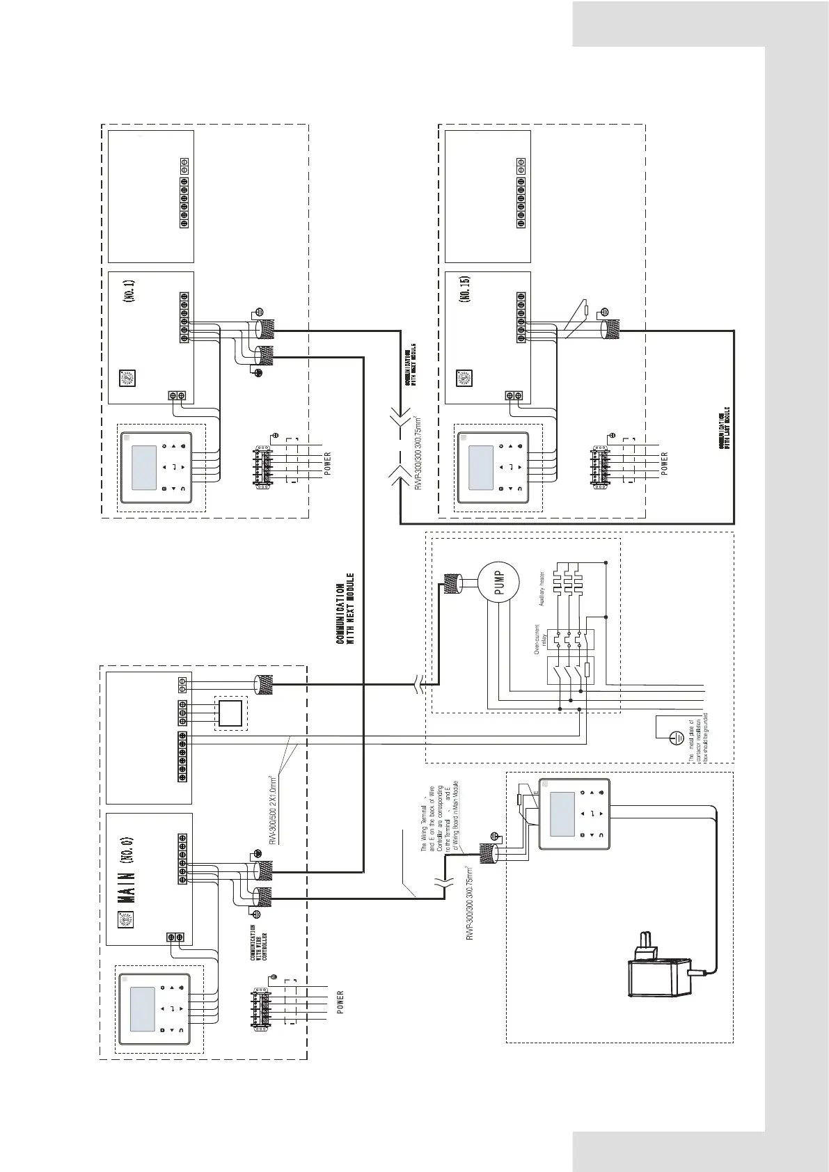
Fig. 8-18 Networking communication schematic of main unit and auxiliary unit for 110KW
CN108
GND
0-10V
GND
IN2
22
L1 L2 L3 N
Th e le ng th o f wi re
sh ou ld b e sh or ter
th an 5 00 m
10 0Ω
Notes
The wiring diagram of auxiliary heaters
is just for reference ,please follow the
instructions of corresponding auxiliary
heater products.
Please choose such accessory as power
wire , switch of auxiliary heater according to
the actual parameter of products and national
Contactor
Power Transformer
OUTPUT:8.5 V
~
for pipeline
MAIN CONTROL
WIRECONTROLER
X Y
X
Y
X
Y
XT3
POWER 380-415V 3N~50Hz
POWER 380-415V 3N~50Hz
ENC1
AC1
AC2
MAIN CONTROL
WIRECONTROLER
X
Y
E
RD
YE
BK
BR
WH
RVV-300/500 5X50mm
2
X
Y
E
AC1
AC2
RD
YE
BK
BR
WH
Main board
Slave board
CN22
CN46
CN119
HEAT1
POWER 380-415V 3N~50Hz
RVV-300/500 5X50mm
12 0Ω
MAIN CONTROL
WIRECONTROLER
XT3
ENC1
X
Y
E
RD
YE
BK
BR
WH
X
Y
E
AC1
AC2
RD
YE
BK
BR
WH
Main board
Slave board
CN22
CN46
CN119
HEAT1
MAIN CONTROL
WIRECONTROLER
XT3
ENC1
X
Y
E
RD
YE
BK
BR
WH
X
Y
E
AC1
AC2
RD
YE
BK
BR
WH
Main board
Slave board
CN22
CN46
CN119
HEAT1
2
POWER 380-415V 3N~50Hz
RVV-300/500 5X50mm
2
SLAVE
SLAVE
CN108
CN108
CN125
COM
NC
NO
3-way
valve
 Loading...