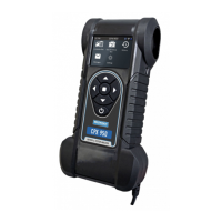
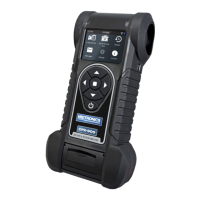
CPX-950
www.midtronicseurope.com
Midtronics BV Hoofdveste 6-8 3992DG Houten
8
9
2 – 12V Battery
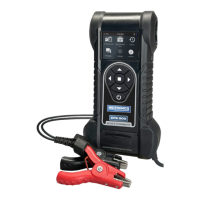
CPX-950
12V Baery
Use 12V Battery to perform Battery Tests on car batteries. Using test parameters
the battery can be tested both in vehicle and out of vehicle. Press to
return to the previous screen, select options and when necessary,
o
to enter or
continue to the next step. Use BACK to return to the Main Menu.
Battery Test
1. Connect to the battery.
2. Battery Test Setup - Edit the displayed vehicle and battery information.
Battery Location Under Hood Out of Vehicle Under Seat
Test Location*
1
Battery Post Jump Start Post Jump Start Post (BMS)
Predened rating*
2
A list of known Ford batteries, plus at the end of the list a possibility to
enter a battery manually.
Battery Type EFB AGM SLI
Battery Units EN
SAE
IEC
DIN
JIS
EN2
Battery Rating
Hold down or to increase scrolling
speed.
VIN Insert the last 5 number of the Vehicle ID
number (VIN). This step is optional.
*
1
Test location is not shown in Setup menu when 'Out of Vehicle' was selected.
*
2
When a predened rating is selected, 'Type', 'Battery Units' and 'Rating' are not editable in
the Setup menu.
Rating Description Range
EN European Norms. The battery is required to meet a voltage of 7.5V after 10
seconds
100 to 3000
SAE Society of Automotive Engineers norm. The test species that the battery at a
temperature of –18°C will deliver a current equal to the Cold Cranking Amps
for 30 seconds with the voltage staying above 7.2 volts
100 to 3000
IEC International Electrotechnical Commission norm. The IEC test is performed
at -18°C
100 to 1000
DIN Deutsche Industrie-Norm 100 to 1000
EN2 European Norms 2. Performing a different second discharge than with EN. 100 to 3000
JIS Japanese Industrial Standard test, carried out at -15°C. A list is shown
Select Start to advance to the battery test.
3. Temperature - you are requested to aim the temperature sensor at the battery. Then click 'Cap-
ture' The test is started.
Battery Test Results
2 – 12V Battery
• Corroded, loose, or damaged cables and connections. Repair or replace them as needed.
• Corrosion on the battery terminals, and dirt or acid on the case top. Clean the case and termi-
nals using a wire brush and a mixture of water and baking soda.
• Low electrolyte level. If the electrolyte level is too low, add distilled water to ll up to ½ above
the top of the plates and fully charge the battery. Do not overll.
• Corroded or loose battery tray and hold-down xture. Tighten or replace as needed.
Testing Out-of-Vehicle (Battery Test)
The preferred battery test location is in the vehicle (Under Hood, Under Seat). However, if you plan
to test out of the vehicle:
• Always disconnect the negative cable from the battery rst and reconnect it last.
• Always use a carry tool or strap to lift and transport the battery.
Failure to properly install lead terminal
adapters, or using adapters that are dirty or
worn, may cause false test results.
When testing side-post or Group 31 batteries, always use lead terminal adapters
provided with the tester—do not test at the battery’s steel bolts. To avoid damage,
never use a wrench to tighten the adapters more than ¼ turn.
Testing Under Hood or Under Seat
The preferred test position is at the battery posts. If you must test at a Jump (start) Post location, it
should have both a positive and negative post.
System Test
Before starting the test, inspect the alternator drive belt. A belt that is glazed or worn, or lacks the
proper tension, will prevent the engine from achieving the rpm levels needed for the test.
At the start of the test, place the vehicle transmission in PARK, make sure all vehicle accessory loads
are o, the key is not in the ignition, and the doors are closed.
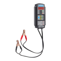
Connecting To The Battery
Connect the red clamp to the positive (+) terminal and the black clamp to the negative (–) terminal.
If you connect the clamps in the wrong polarity (red to negative or black to positive), the analyzer
displays "CLAMPS REVERSED!" Reconnect the clamps.
To make sure both sides of the clamps are gripping the terminals, rock the each clamp back and
forth. A poor connection will prevent testing, and the analyzer displays the message CHECK
CONNECTION. If the message reappears after you have correctly reconnected the clamps, clean the
terminals and reconnect.