Midtronics Inc. 7000 Monroe Street Willowbrook, IL 60527
www.midtronics.com
6
Chapter 1: Introduction DSS-7000
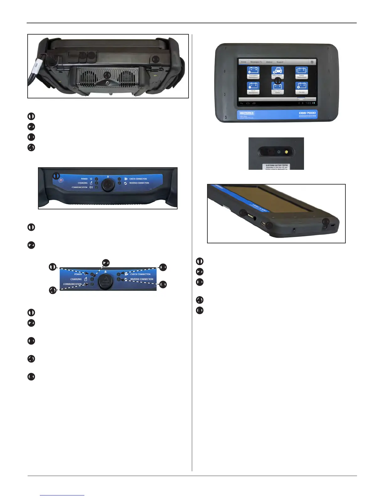
Top View
Charger Port: Plug in point for the Diagnostic Device charger.
USB port
RJ45 Connector: For accessory cable connection.
Temperature Sensor: For measuring the ambient tem-
perature of a battery during the testing procedure.
Control Panel
Power Button: For powering up analyzer when not con-
nected to a battery.
Tablet Controller Release Button: Press to release the
Tablet Controller module from the Diagnostic Device.
Status LEDs
Power: Green when analyzer is on.
Charging: Red - analyzer charging or needs charging, or
Green - fully charged.
Check Connection: Red - check clamp connection, or
Green - clamp connection OK.
Communication: Flashes Blue when the Diagnostic De-
vice is communicating with the Tablet Controller.
Reverse Connection: Red - clamps reversed, or Green -
clamps OK.
Tablet Controller
Front View
Rear View
Side View
Touch Screen: Primary user interface.
Camera: For VIN scanning and identication
Diagnostic Device Connection: For when the Tablet
Controller is docked with the Diagnostic Device.
Charger Port: Plug in point for the Diagnotic Device charger.
Power Button: For turning the Tablet Controller on and
o independent of the Diagnostic Device.